
Equipment and method for lifting and filling low-temperature geothermal water source in same well

A low-temperature, geothermal technology, applied in geothermal power generation, collectors using groundwater as working fluid, etc., can solve the problems of short geological contact time, insufficient heating, and few recharge layers, etc., to increase the contact distance and Area, energy consumption reduction, the effect of prolonging the heating time

Pending Publication Date: 2022-04-15
王心海 +1
View PDF3 Cites 0 Cited by
  • Summary
  • Abstract
  • Description
  • Claims
  • Application Information

AI Technical Summary

Problems solved by technology

[0005] The invention provides a device and method for raising and irrigating low-temperature geothermal water sources in the same well, and its purpose is to solve the problems of fast recharge speed, short contact time with geology and insufficient heating caused by the small number of recharge layers in the existing single well.

Method used


Image

  • Equipment and method for lifting and filling low-temperature geothermal water source in same well

Examples


Embodiment 1

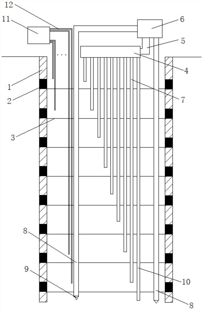
[0031] Embodiment 1: the well pipe 1 with a length of 130 meters, a well diameter of 0.8 meters, and a well pipe of 0.42 meters is drilled underground to the aquifer, and the well distance is greater than or equal to 100 meters. , the 30th meter, the 45th meter, the 60th meter, the 75th meter, the 90th meter, the 105th meter, and the 120th meter are respectively provided with a metal clapboard 3 to form a water-resistant layer, so that the well pipe forms eight levels. Each level of well pipe is connected by solid pipe 1 and mesh pipe 2. The solid pipe 1 is the well pipe without through holes in the pipe wall; the mesh pipe 2 is the well pipe with multiple through holes in the pipe wall; the diameter design of the through holes It is 1-2cm. This design is because the weight of the water brings a certain pressure, so that the silt in the well pipe is easy to discharge outside the pipe and does not stay in the well pipe; The effect will return to the pipe wall, but will bring m...

Embodiment 2

[0037] A well pipe with a length of 180 meters, a well diameter of 1 meter, and a diameter of 0.5 meters is lowered underground to the aquifer by drilling technology, and the well spacing is greater than or equal to 100 meters. The 45th, 65th, 85th, 105th, 125th, 145th, and 165th meters are respectively provided with a metal partition 3 to form a water-resisting layer, so that the well pipe forms eight stages. Each level of well pipe is connected by solid pipe 1 and mesh pipe 2. The solid pipe 1 is the well pipe without through holes in the pipe wall; the mesh pipe 2 is the well pipe with multiple through holes in the pipe wall; the diameter design of the through holes It is 1-2cm. This design is because the weight of the water brings a certain pressure, so that the silt in the well pipe is easy to discharge outside the pipe and does not stay in the well pipe; The effect will return to the pipe wall, but will bring more sediment, which is not as effective as the aforementione...


PUM


Abstract

The invention relates to the technical field of developing, utilizing and extracting an underground water heat source and recharging, in particular to equipment and a method for lifting and charging a low-temperature geothermal water source in the same well, a well pipe is of a hierarchical structure, the pipe wall of each stage of well pipe is formed by connecting a solid pipe and a mesh pipe, and the stages of the well pipe are separated by partition plates and are divided into eight stages; the water segregator is connected with a group of graded water return pipes with different lengths, and each graded water return pipe is respectively inserted into each stage of the well casing; a water lifting pipe arranged in the well pipe penetrates through the partition plate in the axial direction of the well pipe and is inserted into the bottom of the well pipe, the tail end of the water lifting pipe is connected with a submersible pump, and the other end of the water lifting pipe is connected with a heat exchanger. The method has the advantages that the recharge water can permeate into the ground at different levels of layers, the resistance of underground pressure to the recharge water is reduced, and pressurization equipment is omitted; meanwhile, the underground water level can be prevented from falling, and the ground and surrounding buildings are not affected.

Description

Technical field: [0001] The invention mainly relates to the technology of developing, utilizing, extracting and recharging groundwater heat sources, and in particular relates to a device and method for raising and irrigating low-temperature geothermal water sources in the same well. Background technique: [0002] As the use of geothermal resources continues to deepen and increase in various places, due to the characteristics of different amounts, different times, and asynchronous characteristics of conventional technology for recharge and water extraction, it has the following problems: 1. Environmental protection issues: heat pollution, soil pollution. Long-term plundering of geothermal water, insufficient recharge of underground vacant layers and insufficient soil compensation have resulted in the intrusion of surface pollutants, especially the phenomenon of seawater intrusion into hot spring geological layers in coastal areas; Time cannot be compensated by medium and spac...

Claims


Application Information

Patent Timeline
Patent Type & Authority Applications(China)
IPC IPC(8): F24T10/20
CPCY02E10/10
Inventor 王心海董玉茹
Owner 王心海
Learn More