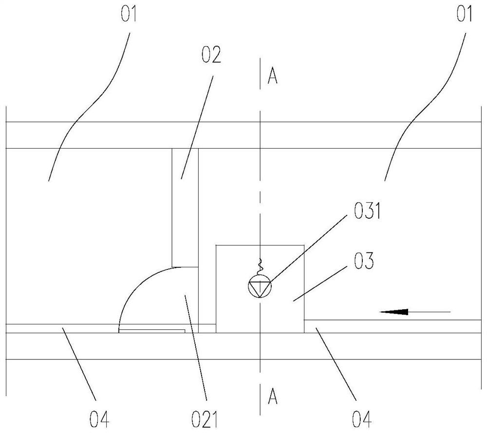
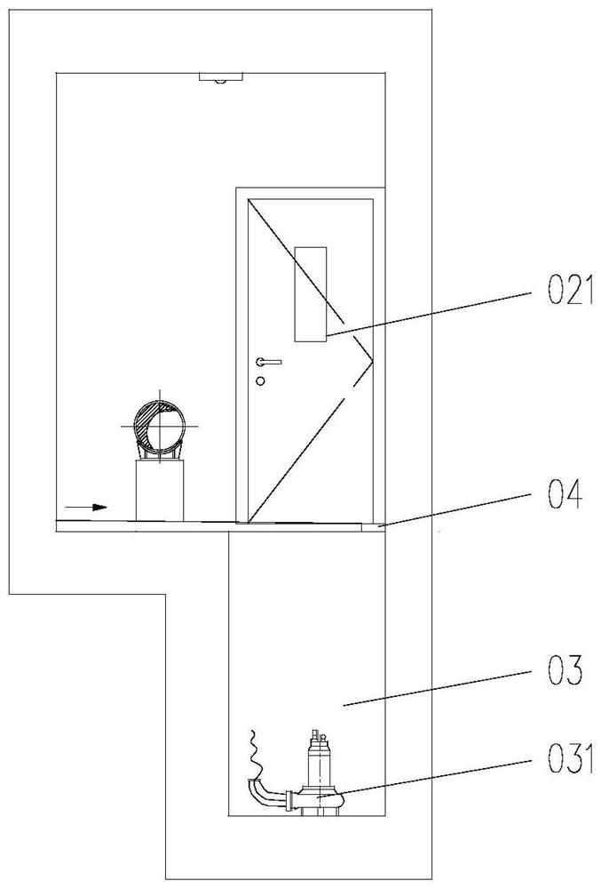
Drainage structure of comprehensive pipe gallery natural gas cabin and comprehensive pipe gallery
A technology for integrated pipe gallery and drainage structure, applied in drainage structures, underwater structures, infrastructure engineering, etc., can solve problems such as potential safety hazards, achieve high safety, avoid diffusion and leakage, and reduce the effect of installed equipment
- Summary
- Abstract
- Description
- Claims
- Application Information
AI Technical Summary
Problems solved by technology
Method used
Image
Examples
Embodiment Construction
[0039] In order to have a clearer understanding of the technical features, purposes and effects of the present invention, the specific implementation manners of the present invention will now be described with reference to the accompanying drawings.
[0040] Such as Figure 5 to Figure 8As shown, this embodiment provides a drainage structure for the natural gas tank of the integrated pipe gallery, which is applied to the integrated pipe gallery 1 with the natural gas tank 11 . The drainage structure of the natural gas tank of the comprehensive pipe gallery includes a drainage channel 2, which is arranged in the bottom plate 15 of the comprehensive pipe gallery 1, and the two ends of the drainage channel 2 are respectively located on both sides of the firewall 12 of the comprehensive The drainage gutters 14 on both sides are connected. The height of the first end of the drainage channel 2 is higher than that of the second end, and the channel part between the two ends of the d...
PUM
 Abstract
Description
Claims
Application Information
 - Generate Ideas
- Intellectual Property
- Life Sciences
- Materials
- Tech Scout
- Unparalleled Data Quality
- Higher Quality Content
- 60% Fewer Hallucinations
Browse by: Latest US Patents, China's latest patents, Technical Efficacy Thesaurus, Application Domain, Technology Topic, Popular Technical Reports.
© 2025 PatSnap. All rights reserved.Legal|Privacy policy|Modern Slavery Act Transparency Statement|Sitemap|About US| Contact US: help@patsnap.com


