
Network camera based on power carrier transmission technology

A technology of network camera and transmission technology, which is applied in the field of network cameras based on power carrier transmission technology, can solve the problems of increasing network bandwidth pressure, increasing video capacity, and high investment costs, so as to enhance flexibility, avoid crashes, and engineering The effect of cost reduction

Active Publication Date: 2013-04-17
ZHEJIANG NEW ZAILING TECH CO LTD
View PDF0 Cites 1 Cited by
  • Summary
  • Abstract
  • Description
  • Claims
  • Application Information

AI Technical Summary

Problems solved by technology

[0002] In the prior art, the higher the resolution and ultra-high definition of the high-definition surveillance camera, the bit stream will also increase during data transmission, increasing the pressure on network bandwidth, doubling the data flow, and increasing the recording capacity. On the one hand, it will bring pressure to network storage, the requirements for central control, management software and hardware performance will increase exponentially, and the workload for management and post-event analysis of recorded video images will also increase exponentially, and the investment cost will be high.

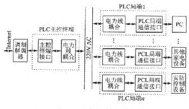
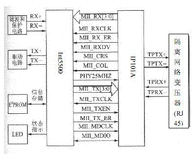
Method used


Image

  • Network camera based on power carrier transmission technology
  • Network camera based on power carrier transmission technology

Examples


Embodiment Construction

[0013] In order to deepen the understanding of the present invention, the present invention will be further described below in conjunction with the embodiments and accompanying drawings. The embodiments are only used to explain the present invention and do not constitute a limitation to the protection scope of the present invention.

[0014] refer to Figure 1 to Figure 2 , the present invention is based on the network camera of power carrier transmission technology, comprises network camera, communication network and remote monitoring client end, and network camera comprises lens, microphone, image sensor, sound sensor, A / D converter, image sound coder, controller and a network server, the communication network includes a modem, a PLC main control terminal and a PLC local end, the PLC main control terminal includes a main control terminal interface module and a first-level coupling circuit, the PLC local end includes a second-level coupling circuit and a local end communicatio...


PUM


Abstract

The invention relates to a network camera based on a power carrier transmission technology. The network camera based on the power carrier transmission technology comprises a network camera, a communication network and a remote monitoring client, wherein the communication network comprises a modulator-demodulator, a programmable logic controller (PLC) main control terminal and a PLC local side; the PLC main control terminal comprises a main control terminal interface module and a primary coupling circuit; the PLC local side comprises a secondary coupling circuit and a local side communication interface module; a local area network or an INTERNET of a computer is connected with the network camera and the modulator-demodulator; one end of the main control terminal interface module is connected with the modulator-demodulator, and the other end of the main control terminal interface module is connected with a 220V alternating-current power wire through the primary coupling circuit; and oneend of the local side communication interface module is connected with the 220V alternating-current power wire through the secondary coupling circuit, and the other end of the local side communication interface module is connected with the remote monitoring client. According to the network camera based on the power carrier transmission technology, coaxial cables and huge video distributors are not needed, so the engineering cost is greatly reduced; and far-end monitoring is realized by using network resources, so that the defect of monitoring failure caused by halt and restart is also avoided.

Description

technical field [0001] The invention relates to a network camera, in particular to a network camera based on power carrier transmission technology. Background technique [0002] In the prior art, the higher the resolution and ultra-high definition of the high-definition surveillance camera, the bit stream will also increase during data transmission, increasing the pressure on network bandwidth, doubling the data flow, and increasing the recording capacity. On the one hand, it will bring pressure to network storage, and the requirements for central control and management software and hardware performance will increase exponentially. The workload for management and post-event analysis of recorded video images will also increase exponentially, and the investment cost will be high. Contents of the invention [0003] In view of the above shortcomings, the technical problem to be solved by the present invention is to provide a network camera based on power carrier transmission t...

Claims


Application Information

Patent Timeline
Patent Type & Authority Patents(China)
IPC IPC(8): H04N5/225H04N7/18H04B3/54
Inventor 同军武
Owner ZHEJIANG NEW ZAILING TECH CO LTD
Learn More