
Drafting device

A drafting device and drafting technology, applied to drafting equipment, textiles, papermaking, spinning machines, etc., can solve problems such as difficulties and achieve the effect of less risk of accidents

Active Publication Date: 2019-11-29
TRUETZSCHLER GRP SE
View PDF5 Cites 0 Cited by
  • Summary
  • Abstract
  • Description
  • Claims
  • Application Information

AI Technical Summary

Problems solved by technology

In this case, a part of the ribbon guiding mechanism is between the two supports, which makes access from the longitudinal side extremely difficult, if not impossible.

Method used


Image

  • Drafting device
  • Drafting device
  • Drafting device

Examples


Embodiment Construction

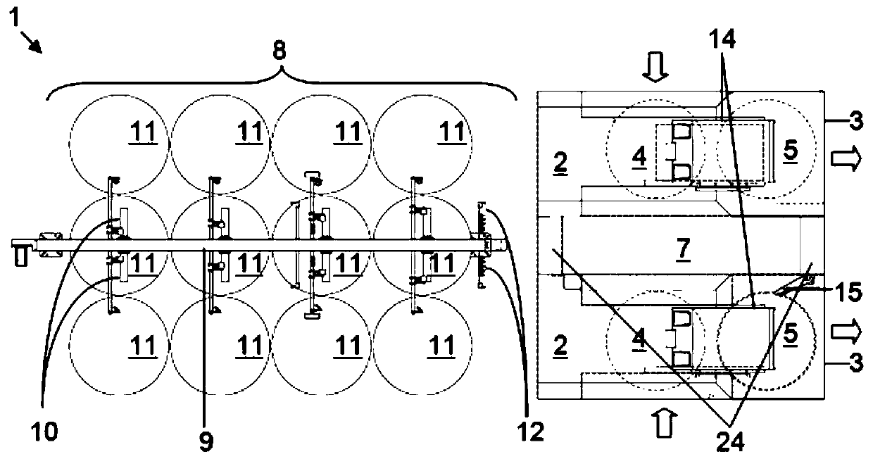
[0033] figure 1 A drafting device 1 according to a first embodiment of the invention is shown in plan view, which is designed as a double-head draw frame.

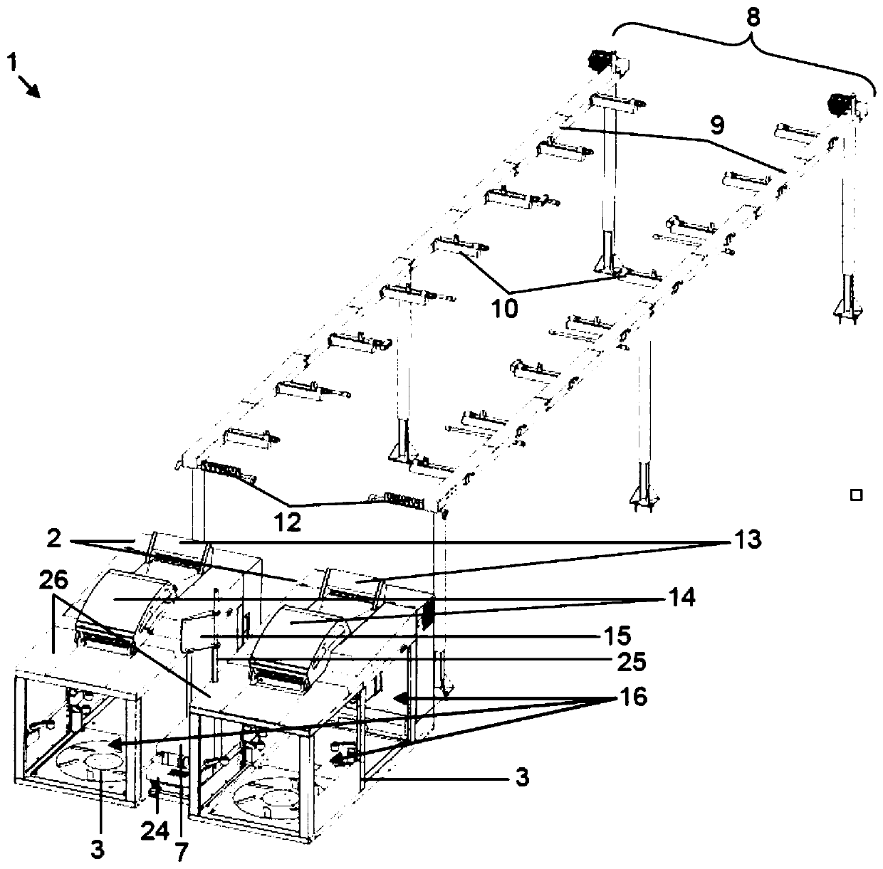
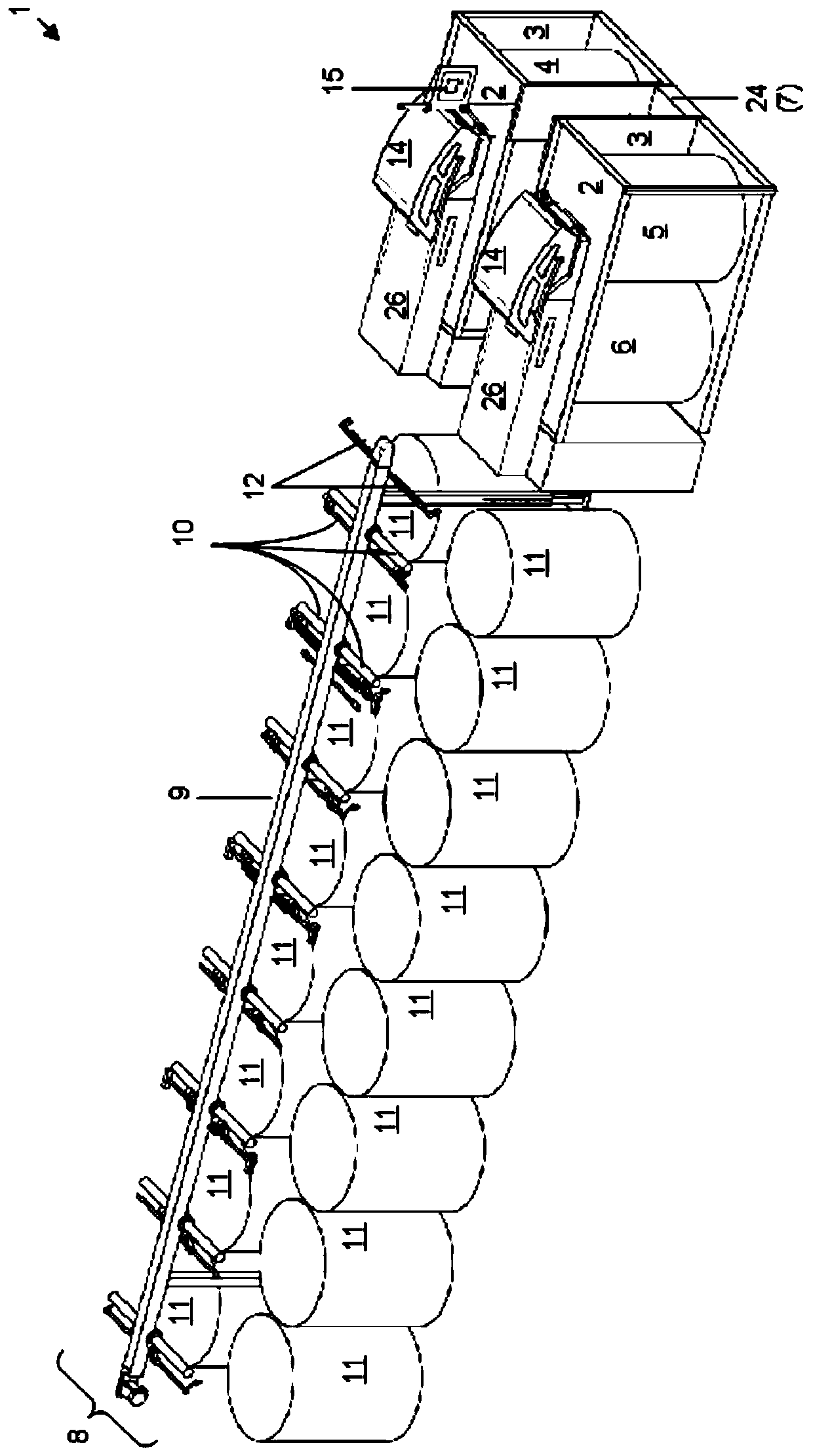
[0034] The double-head draw frame 1 comprises two drafting mechanisms 2 which are arranged above the respective can changer 3 .

[0035] The drafting unit 2 is designed in a conventional manner, ie has drafting rollers and corresponding sensor devices for the thickness of the fiber web. Furthermore, each drafting mechanism 2 has its own, invisible drive. The drives and drafting rollers are preferably arranged below the respective housing cover 14 .

[0036] Each can changer 3 is designed as a linear changer by way of example. That is to say, a correspondingly empty can 4 is viewed along the longitudinal extension of the double-head draw frame 1 according to figure 1 That is to say horizontally, laterally from the outer side of the respective can changing device 3 into the can changing device 3 . this point in figure ...


PUM


Abstract

The invention relates to a drafting device, and the drafting device has two drafting mechanisms. Each drafting mechanism has a feed section, a draft section, an output section and a drive. The feed section is designed to feed the fiber strip from the outside relative to the associated drafting mechanism in the direction of the drafting section of the associated drafting mechanism. This drafting section is designed to draft and homogenize the conveyed fiber web according to predetermined preset values. The delivery section is designed to deliver the drawn and homogeneously processed fiber web out of the associated drafting unit. The drive device is designed to drive the associated section of the drafting mechanism. Furthermore, the drafting mechanism has an operating unit. The operating unit is designed to enable a user to configure and control the operation of the two drafting mechanisms independently of one another.

Description

technical field [0001] The invention relates to a drafting device, that is to say a device, which can for example draw in fiber strips from several cans, then place them side by side, draft them and merge them into a new single The fiber strip preferably has the same width dimension as each individual fiber strip of the drawn-in plurality of fiber strips. In the context of the present application, a width dimension means the extent of the fiber strip in each direction transverse to the longitudinal extent of the fiber strip. Background technique [0002] To draw in the fiber bands, generally a creel device is used, in which the cans are arranged in one or more rows next to each other as viewed along their longitudinal extent. In general, up to ten fiber strips can be drawn into the drafting unit. [0003] The problem is that a large number of draw frames are required within the range of the processing chain from loose fibers, such as cotton fiber bales or man-made fibers, ...

Claims


Application Information

Patent Timeline
Patent Type & Authority Patents(China)
IPC IPC(8): D01H5/70D01H13/32D01H11/00
CPCD01H5/70D01H11/00D01H13/32D01H5/00
Inventor 托马斯·施密茨阿米尼·莱德
Owner TRUETZSCHLER GRP SE
Learn More