A circuit board spraying device
A technology of spraying device and circuit board, which is applied in the direction of spraying device, etc., can solve the problems of increasing manual labor, inconvenient level fixing, circuit board dripping, etc., and achieve the effect of increasing practicability and increasing convenience
- Summary
- Abstract
- Description
- Claims
- Application Information
AI Technical Summary
Problems solved by technology
Method used
Image
Examples
Embodiment 1
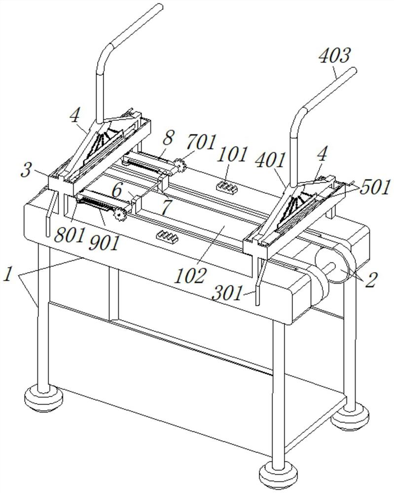
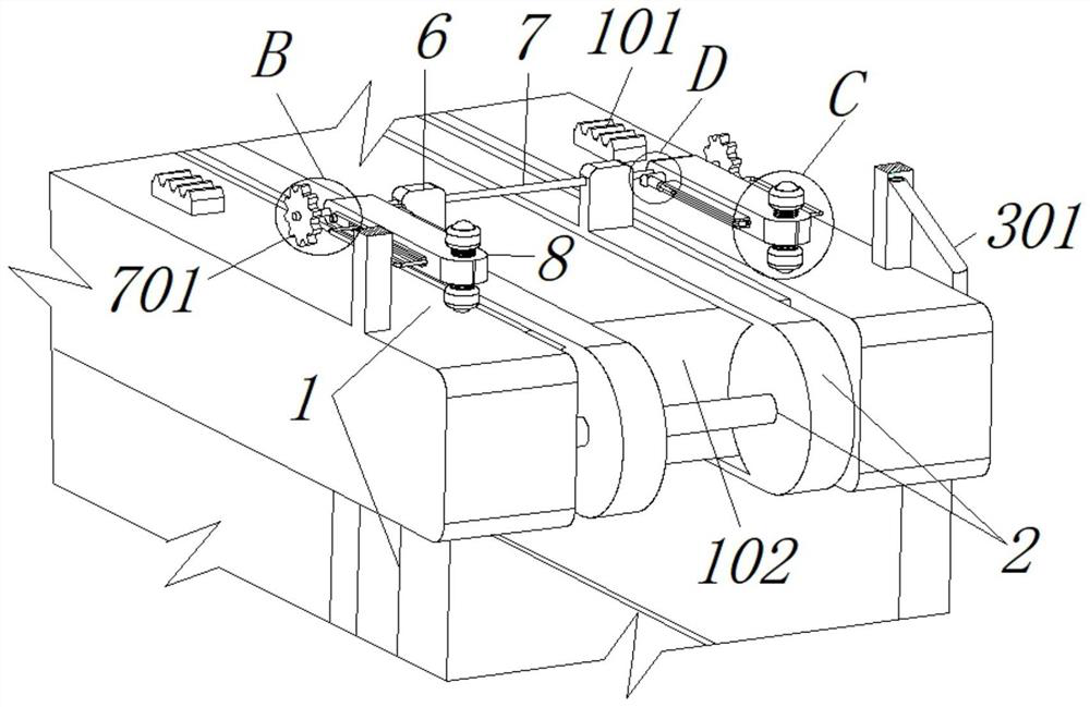
[0034] see Figure 1-6 The clamping mechanism 9 includes a pull rod 901 that is engaged with the inner side of the support plate 8, and a return spring 902 is installed on the outer side of the front end of the pull rod 901, and a rubber block 903 is fixed at the front end of the pull rod 901. The slide plate 1001 is provided with a second spring telescopic rod 1002 on the rear side of the slide plate 1001. The right side of the second spring telescopic rod 1002 is connected with a squeeze telescopic rod 1003. The rear side of 1001 and the end of the second spring telescopic rod 1002 are welded and fixed, the inner side of the slide plate 1001 and the outer side of the circuit board form a mosaic structure, the support plate 8 and the base 1 are parallel to each other, and the top of the base 1 is welded with racks on both sides of the front and back Board 101, and a mounting block 102 is welded on the inside of the base 1. The mounting block 102 is located inside the two spro...
Embodiment 2
[0036] see figure 1 , image 3 , Figure 5 and Figure 7-8 The difference from Embodiment 1 is that the adjustment mechanism 5 includes a bidirectional screw rod 501 whose bearing is connected to the inner side of the box body 3, and the outer side of the bidirectional screw rod 501 is threadedly connected with a slider 502, and a fan-shaped cavity 401 is provided above the connecting plate 4. , and the inner side of the connecting plate 4 is respectively fixed with a branch pipe 402, the top of the fan-shaped cavity 401 is connected with a paint inlet pipe 403, a through hole 404 is opened under the inner side of the connecting plate 4, and the through hole 404 and the branch pipe 402 communicate with each other, and the bottom of the box body 3 There is a connecting pipe 301 running through, and a convex groove 302 is punched at the bottom of the inner side of the box body 3, and the convex groove 302 is in the shape of a square hole. The block 502 and the box body 3 form...
PUM
 Abstract
Description
Claims
Application Information
 - R&D
- Intellectual Property
- Life Sciences
- Materials
- Tech Scout
- Unparalleled Data Quality
- Higher Quality Content
- 60% Fewer Hallucinations
Browse by: Latest US Patents, China's latest patents, Technical Efficacy Thesaurus, Application Domain, Technology Topic, Popular Technical Reports.
© 2025 PatSnap. All rights reserved.Legal|Privacy policy|Modern Slavery Act Transparency Statement|Sitemap|About US| Contact US: help@patsnap.com


