
Coupling lens easy to reduce optical error after assembly

A coupling lens and post-assembly technology, applied in the field of coupling lenses, can solve problems affecting optical path loss, optical errors, changes in optical power output, and affecting optical power output, etc., and achieve the effects of easy processing, production and use, efficient irradiation, and simple and flat structure

Pending Publication Date: 2022-04-12
四川都乐光电科技有限公司
View PDF0 Cites 0 Cited by
  • Summary
  • Abstract
  • Description
  • Claims
  • Application Information

AI Technical Summary

Problems solved by technology

[0003] In many applications, the output optical power of the laser is affected by many factors. First, when the laser is used, it is necessary to use a coupling lens to focus and couple the laser light to increase the coupling efficiency. However, the installation position of the coupling lens and the stability after installation Both will affect the output optical power. Second, during the use of the laser, the change of the ambient temperature will affect the output of the optical power. The main reason is that as the temperature changes, the laser threshold current of the laser also changes, resulting in optical The change of power output, the third factor that affects the change of optical power output is the aging of the laser during use. The reason is also because with the long-term use of the laser, the laser threshold current of the laser also changes, resulting in optical power output change
[0004] In view of the power influence that is easily generated during the laser transmission process, some existing coupling lenses will block the lost part of the optical path to cause refraction or reflection to realize the monitoring and detection of the optical path. After monitoring and detection, it will be the lasing threshold current of the laser The adjustment provides a basis to increase the stability of the optical output power, but the disadvantage is that the optical monitoring of the optical path that is a part of the above-mentioned occlusion loss itself affects the optical path loss and generates optical errors.

Method used


Image

  • Coupling lens easy to reduce optical error after assembly
  • Coupling lens easy to reduce optical error after assembly
  • Coupling lens easy to reduce optical error after assembly

Examples


Embodiment Construction

[0018] The following will clearly and completely describe the technical solutions in the embodiments of the present invention with reference to the accompanying drawings in the embodiments of the present invention. Obviously, the described embodiments are only some of the embodiments of the present invention, not all of them. Based on the embodiments of the present invention, all other embodiments obtained by persons of ordinary skill in the art without making creative efforts belong to the protection scope of the present invention.

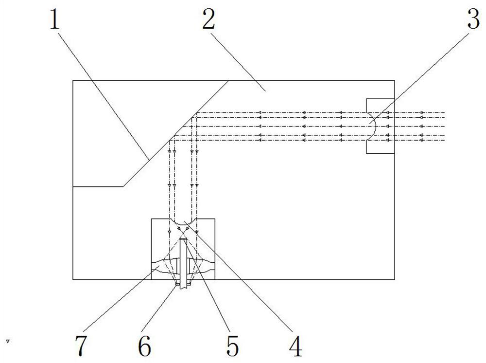
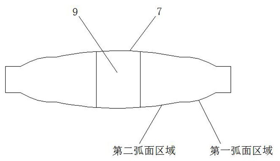
[0019] see Figure 1-4 , an embodiment provided by the present invention: a coupling lens that is easy to reduce optical errors after assembly, including a coupling lens body 2 and a VCSEL laser 5, the coupling lens body 2 is respectively provided with an incident lens 4 and an exit lens 3, The coupling lens body 2 is provided with a reflective surface 1 for the total reflection of the optical path between the incident lens 4 and the exit lens 3....


PUM


Abstract

The invention discloses a coupling lens easy to reduce light error after assembly, comprising a coupling lens body and a VCSEL laser, the coupling lens body is respectively provided with an incident lens and an emergent lens, the coupling lens body is provided with a reflecting surface used for total reflection of a light path between the incident lens and the emergent lens, and the incident lens and the emergent lens are arranged on the coupling lens body. Light emitted by the emergent lens is totally reflected by the reflecting surface and then is focused by the incident lens to form a focus plane. According to the invention, the VCSEL and the optical monitoring PD which are arranged in a high-low staggered manner are utilized to realize accurate full-coverage type VCSEL laser optical path receiving and small-part diffusion energy type optical monitoring PD optical path receiving of an optical path, so that stable and efficient irradiation of the optical path in the coupling lens body can be maintained; the internal structure of the coupling lens body between the VCSEL laser and the emergent lens is simple and flat, the coupling lens body is easy to process, produce and use, optical loss cannot be caused, and the functionality and the coupling effect of the coupling lens are improved.

Description

technical field [0001] The invention relates to the technical field of photoelectric coupling, in particular to a coupling lens which can easily reduce optical errors after assembly. Background technique [0002] With the development of optical fiber communication technology, data centers, search engines, and cloud computing have also developed rapidly. Many communication companies use lasers and optical fibers as the main method to solve a large number of audio, video and data transmissions on the basis of communication networks. To obtain high bandwidth, the light source generally adopts VCSEL laser. [0003] In many applications, the output optical power of the laser is affected by many factors. First, when the laser is used, it is necessary to use a coupling lens to focus and couple the laser light to increase the coupling efficiency. However, the installation position of the coupling lens and the stability after installation Both will affect the output optical power. S...

Claims


Application Information

Patent Timeline
Patent Type & Authority Applications(China)
IPC IPC(8): G02B6/42G02B6/32
Inventor 谢衍琛
Owner 四川都乐光电科技有限公司
Learn More