Composite material launching box guide rail forming mold and guide rail forming method
A composite material and forming mold technology, which is applied in the field of composite material launch box guide rail forming molds and guide rail forming fields to achieve the effects of not being easily deformed, reducing flexural deformation, and reducing forming defects
- Summary
- Abstract
- Description
- Claims
- Application Information
AI Technical Summary
Problems solved by technology
Method used
Image
Examples
Embodiment 1
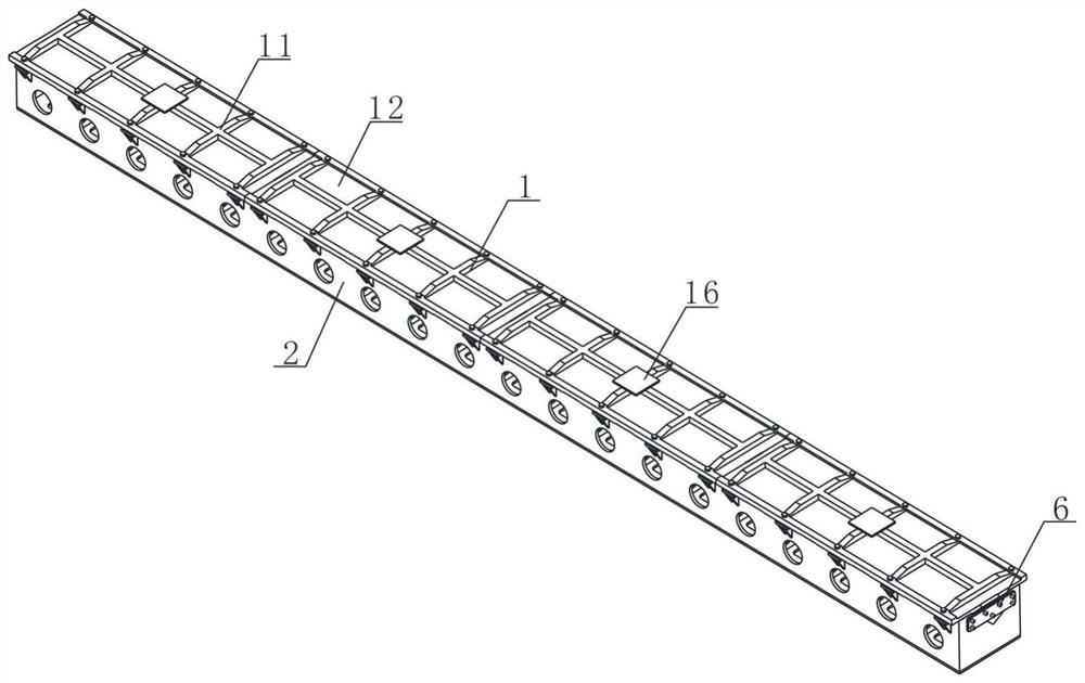
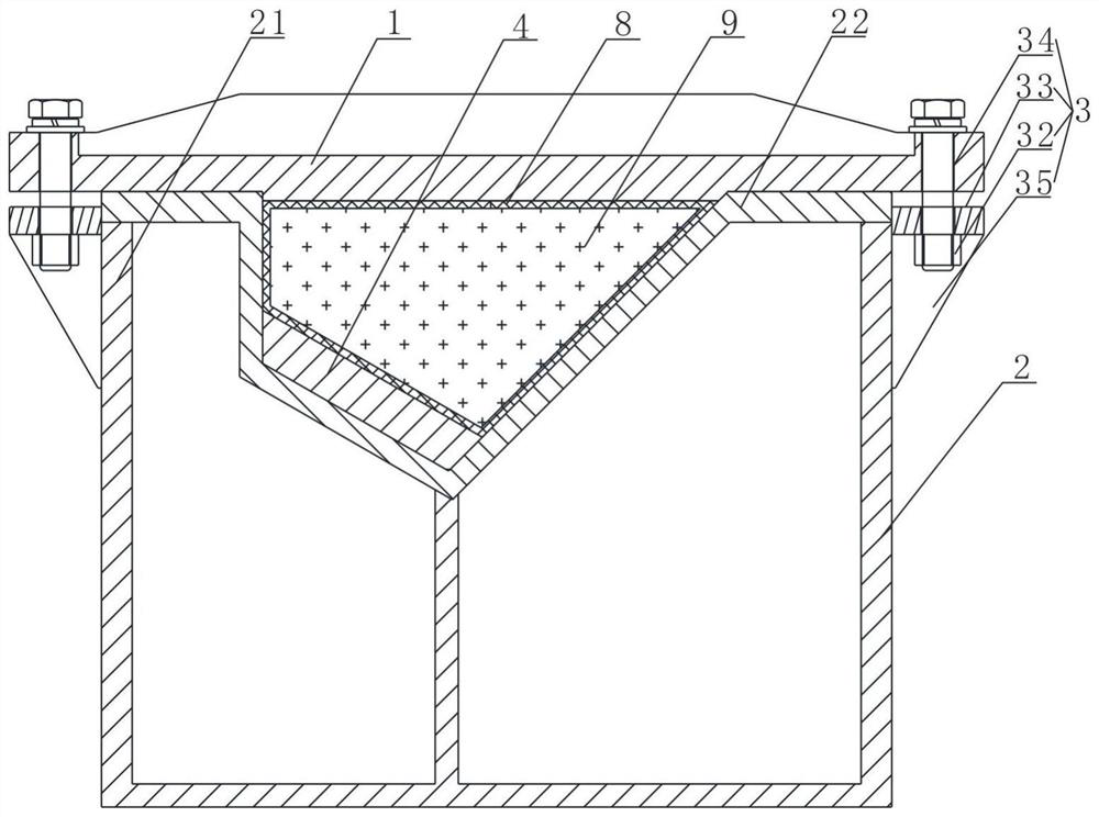
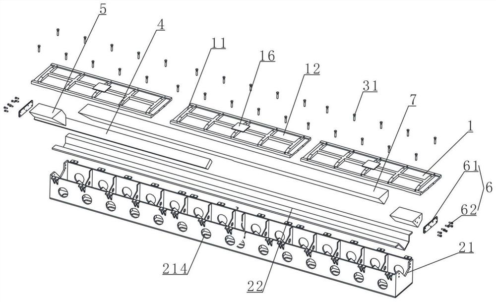
[0049] Such as Figure 1 ~ Figure 3 As shown, the mold for forming the guide rail of the composite launch box includes a lower mold 2 and an upper mold 1 which are arranged oppositely. The lower mold 2 is provided with a guide rail cavity. The bolt assembly 3 is connected, and the pressure generated by the screwing of the bolt assembly 3 causes the guide rail to be formed to be pressurized and solidified in the guide rail cavity.
[0050] The lower mold 2 includes a lower mold frame 21 welded by several steel plates, the lower mold frame 21 is provided with a lower mold panel 22, and the working surface of the lower mold panel 22 is processed by a high-precision numerical control machine tool to ensure dimensional accuracy and surface quality, thereby ensuring The molding dimensional accuracy and surface quality of the guide rail. The guide rail cavity is located on the lower mold panel 22 . During processing, after the lower mold panel 22 and the lower mold frame 21 are wel...
Embodiment 2
[0059] Compared with Embodiment 1, this embodiment differs in that, as image 3 , Figure 5 As shown, the two ends of the cavity of the guide rail are provided with end stoppers 5, and the end stoppers 5 are arranged at both ends of the working surface of the lower die for controlling the length of the guide rail and the shape of the end face of the guide rail. The working surface of the lower mold refers to the bottom surface of the molding cavity.
[0060] The end block 5 is installed on the lower die 2 through the block connecting assembly 6. One end of the lower die panel 22 is provided with an insert 4. The block connecting assembly 6 includes a connecting plate 61 and a plurality of fastening screws 62. The connecting plate 61 passes through The fastening screw 62 fixes the end block 5 to one end of the lower mold frame 21 .
[0061] Both ends of the end block 5 and the fixing frame 211 are provided with a plurality of threaded holes, and the threaded holes on the fixi...
Embodiment 3
[0064] Compared with Embodiment 2, this embodiment differs in that, as Figure 8 As shown, both the insert 4 and the end stopper 5 are provided with mirror-image symmetrical parts to realize symmetrical rail molding. Since the guide rails of the launching box are usually symmetrical parts, by designing mirror-image symmetrical inserts 4 and end stoppers 5, it is possible to use one set of molds to form two symmetrical guide rails. Part 4 and end stopper 5 to form another symmetrical guide rail. The end block 5 and the insert 4 are threadedly connected to the connecting piece, the screw and the lower die.
PUM
 Abstract
Description
Claims
Application Information
 - R&D
- Intellectual Property
- Life Sciences
- Materials
- Tech Scout
- Unparalleled Data Quality
- Higher Quality Content
- 60% Fewer Hallucinations
Browse by: Latest US Patents, China's latest patents, Technical Efficacy Thesaurus, Application Domain, Technology Topic, Popular Technical Reports.
© 2025 PatSnap. All rights reserved.Legal|Privacy policy|Modern Slavery Act Transparency Statement|Sitemap|About US| Contact US: help@patsnap.com


