
Welding device and welding method for fixed contact assembly of molded case circuit breaker

A technology of molded case circuit breaker and welding device, applied in welding/welding/cutting items, auxiliary devices, welding equipment, etc., can solve the problems of high production cost, bracket annealing, low welding efficiency, etc., and achieve good welding quality consistency , good welding performance, the effect of improving production efficiency

Pending Publication Date: 2022-04-12
ZHEJIANG FUDA ALLOY MATERIALS TECH CO LTD
View PDF0 Cites 0 Cited by
  • Summary
  • Abstract
  • Description
  • Claims
  • Application Information

AI Technical Summary

Problems solved by technology

[0005] If induction brazing is used, this process has the characteristics of welding multiple parts at one time, but when the contact and arc striking angle are heated at the same time, since the arc striking angle is made of copper-plated iron and the contact is made of silver graphite, the arc striking angle will heat first To the red state, when the solder reaches a completely melted state, there will be a problem of overburning at the arc striking angle, which will affect the welding appearance of the product and the quality of the electroplating. Close to the bending position of the bracket, first heat the bracket to a red state, melt the solder through the heat conduction of the bracket itself, and then complete the welding between the arc strike angle and the bracket, which will lead to severe annealing of the bracket and a large drop in material hardness. The deformation of the bracket occurs during subsequent transportation, electroplating and other operations, which ultimately affects the performance of the product
[0006] If the traditional metal electrode direct resistance brazing process is used, the welding of the bracket and the contact must be completed first. Usually, in order to ensure the welding strength of the product, there will be obvious solder overflow around it after static contact welding. In the arc angle, there will inevitably be a certain assembly gap between the arc strike angle and the contact, but in order to ensure the performance of the molded case circuit breaker switch product, the customer clearly requires the static contact and arc strike angle in the static component drawing There should be no obvious gap after welding, so it is necessary to polish the solder at the contact position between the contact and the arc starting angle after the contact welding is completed, so as to ensure that the contact and the arc starting angle can fully contact before completing the contact between the arc starting angle and the arc starting angle. The welding of the bracket, such a welding process leads to poor product welding quality consistency and low welding efficiency
At the same time, the direct resistance brazing process adopts the upper and lower electrode structures. The specific method is that the upper electrode presses the upper surface of the contact or the iron-plated copper arc starting angle, and the lower electrode needs to be inserted into the U-shaped structure of the bracket to support the assembly and transmit current and The function of pressure. When using this welding process, the welding heat will be concentrated on the interface between the electrode and the part. Due to the large heat and pressure, the contact and arc starting angle need to be welded step by step. The position of the starting arc angle is close to each other, so the front welding process will affect the subsequent welding process. In addition, the lower electrode is a cantilever beam-type overhanging structure. From the perspective of mechanical structure, it is equivalent to acting on the electrode during the product welding process. A torque, under the action of welding pressure, the position where the lower electrode protrudes out of the electrode base will bend or even break. When this process is welded, the service life of the lower electrode is low, the welding efficiency is low and the production cost is high, which is not conducive to mass production. and economic control

Method used


Image

  • Welding device and welding method for fixed contact assembly of molded case circuit breaker
  • Welding device and welding method for fixed contact assembly of molded case circuit breaker
  • Welding device and welding method for fixed contact assembly of molded case circuit breaker

Examples


Embodiment Construction

[0047] The technical solutions of the present invention will be clearly and completely described below in conjunction with the accompanying drawings. Apparently, the described embodiments are some of the embodiments of the present invention, but not all of them. Based on the embodiments of the present invention, all other embodiments obtained by persons of ordinary skill in the art without making creative efforts belong to the protection scope of the present invention.

[0048] In the description of the present invention, it should be noted that the terms "center", "upper", "lower", "left", "right", "vertical", "horizontal", "inner", "outer" etc. The indicated orientation or positional relationship is based on the orientation or positional relationship shown in the drawings, and is only for the convenience of describing the present invention and simplifying the description, rather than indicating or implying that the referred device or element must have a specific orientation, ...


PUM


Abstract

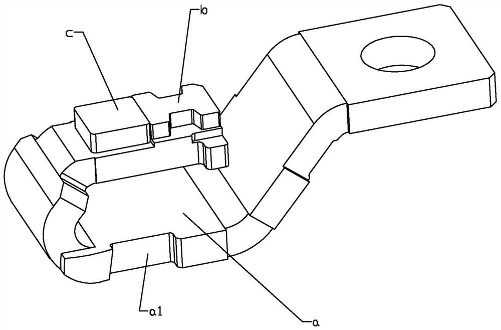
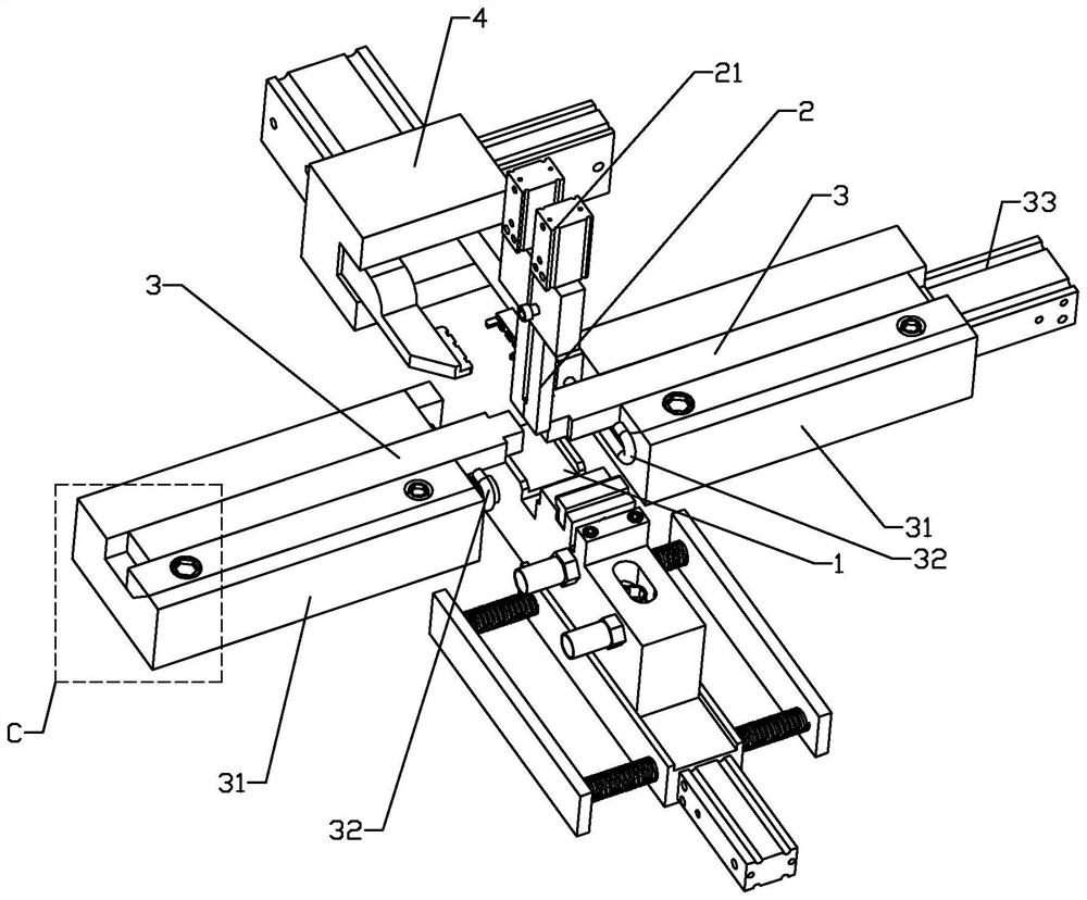
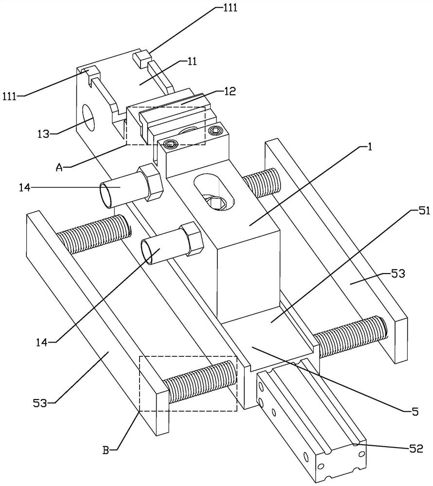
The welding device comprises a support supporting seat, a ceramic pressing rod and two electrodes, the support supporting seat is used for supporting a support, the ceramic pressing rod presses an arc striking angle and a contact to the support, and the two electrodes abut against the two sides, opposite to the arc striking angle and the contact, of the support respectively. By the adoption of the scheme, the welding device and method for the fixed contact assembly of the molded case circuit breaker can complete the high-quality welding process of three parts made of different materials such as a support, a contact and an arc striking angle at a time, welding flux overflows evenly on the appearance of a contact assembly product, the welding brazed rate is larger than or equal to 85%, and the welding quality is improved. And the shear force and metal phase performance indexes are good.

Description

technical field [0001] The invention relates to the field of welding electric contact element processing, in particular to a welding device and a welding method for a static contact assembly of a molded case circuit breaker. Background technique [0002] A circuit breaker is a switching device that can close, carry and break current under normal circuit conditions and can close, carry and break current under abnormal circuit conditions within a specified time. Circuit breakers are divided into high-voltage circuit breakers and low-voltage circuit breakers according to their scope of use. The division of high and low voltage boundaries is relatively vague. Generally, those above 3kV are called high-voltage electrical appliances. [0003] Circuit breakers can be used to distribute electric energy, start asynchronous motors infrequently, protect power lines and motors, and automatically cut off the circuit when they are severely overloaded, short-circuited, or under-voltage. It...

Claims


Application Information

Patent Timeline
IPC IPC(8): B23K1/00B23K3/00B23K3/08B23K101/36
Inventor 申志刚程霞胡均高向坤铃万超明亮王新民刘辉张加林彭承毕
Owner ZHEJIANG FUDA ALLOY MATERIALS TECH CO LTD
Learn More