


Quick Research
Generate reliable direction feasibility study reports for your R&D in just a few steps.

Technical Q&A
Discover and master advanced knowledge NOW. Basics, ideas, possibilities, all at once.

Find Solutions
As an expert in R&D theories, this can generate solutions to your technical problems instantly.

Evaluate Feasibility
Analyze your overall solution with one click, know your potential R&D risks in advance.

Monitor Landscape
Get weekly tech updates, stay abreast of the latest tech innovations and key insights.
Self-aligning rail type impact massage machine core
An orbital, self-aligning technology, applied in vibration massage, massage auxiliary products, physical therapy, etc., can solve the problems of large processing volume and easy wear of piston rod and piston seat, and solve the difficulty of processing and assembly, Reduced wear, flexible movement and fit
- Summary
- Abstract
- Description
- Claims
- Application Information
AI Technical Summary
Problems solved by technology
Method used
Image

Examples
Embodiment 1
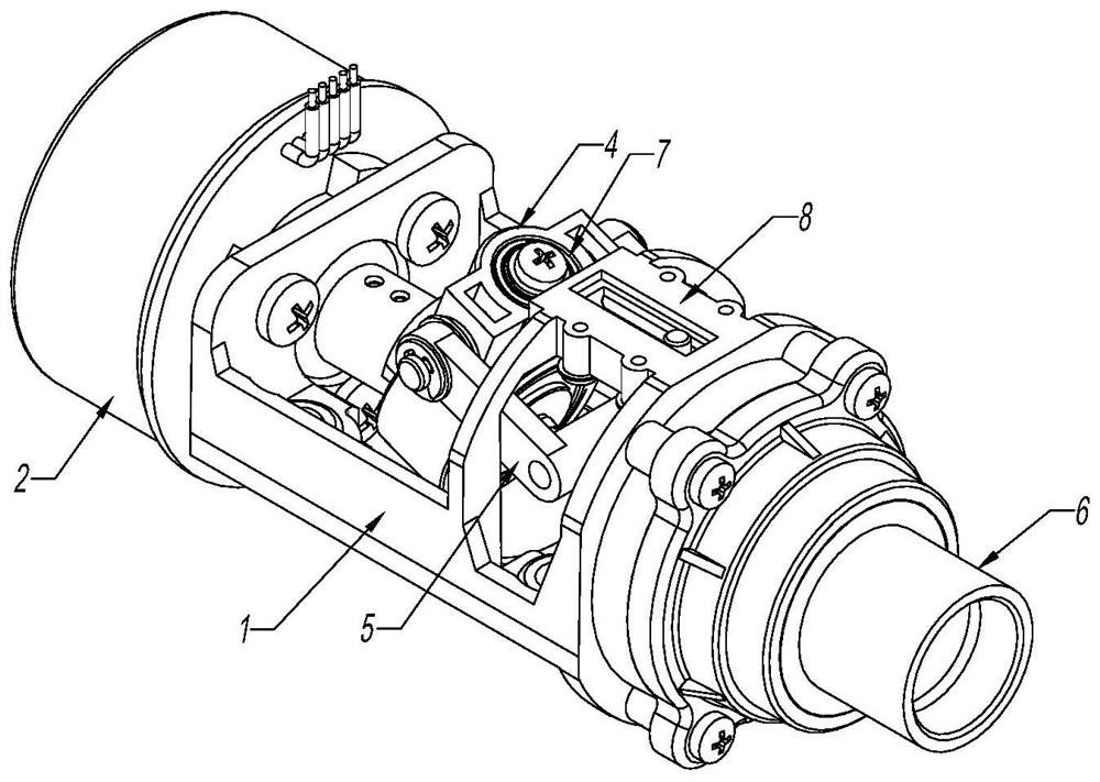
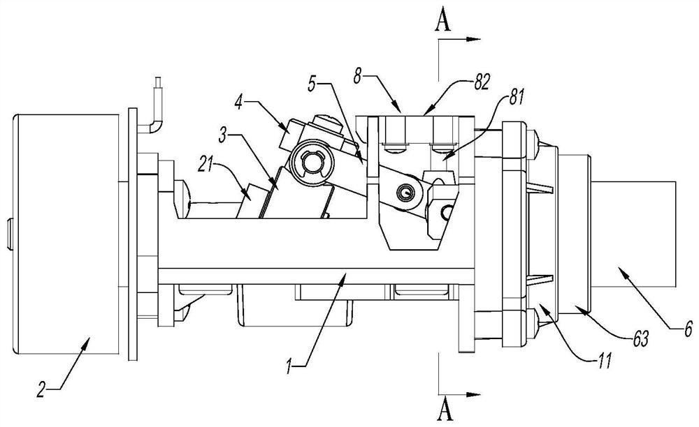
[0034] refer to Figure 1 to Figure 5 , a self-aligning orbital impact massage movement, including a core frame 1, a motor 2, an oblique shaft 21, a swing block 3, a universal shaft joint 4, a connecting rod 5, an impact shaft 6 and an impact bushing 61; the motor 2 and The impact shaft sleeve 61 is correspondingly fixed on the two ends of the core frame 1, and the impact shaft 6 is movably installed in the impact shaft sleeve 61, and one end extending out of the impact shaft sleeve 61 is used for positioning the massage head, and the rear end is hinged with the connecting rod 5; The mandrel 21 is locked on the output shaft of the motor 2 for rotational movement; the swing block 3 is fixed on the inclined mandrel 21 through the bearing 7, and the shaft protrusion 31 on the swing block 3 is connected with the cardan shaft joint 4 through the bearing 7, The universal shaft joint 4 is hinged with the connecting rod 5, which converts the rotational power of the motor 2 into the fo...
Embodiment 2
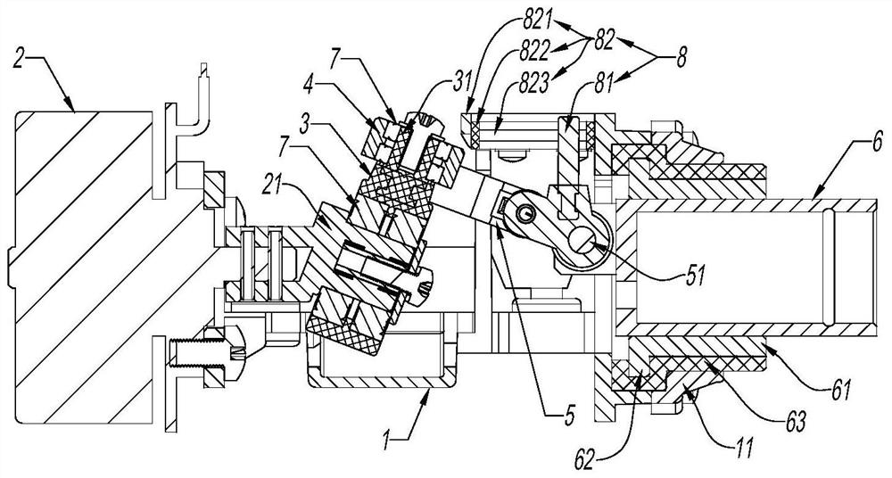
[0041] refer to Figure 6 and Figure 7 , the overall structure is the same as the previous example, except that the self-aligning rod 81 is inserted and fixed in the radial direction of the impact shaft 6, and the groove frame 821 is integrally formed on the front part of the core frame 1, which improves the rigidity and reduces the amount of assembly; the rail seat A pair of sliding cores 823 in 822 is a cylindrical structure, and the centerline is parallel to the centerline of the impact axis 6; in fact, the aligning rod 81 is only in tangential contact with the sliding cores 823, which is close to linear contact, reducing resistance and noise.
[0042] In accordance with the structure of this embodiment, there are two connecting rods 5, one end is symmetrically clamped on the rear end of the impact shaft 6, and hinged by the hinge shaft 51, and the other end is symmetrically clamped on both sides of the universal joint 4, and hinged on the universal joint 4. On the trunni...
Embodiment 3
[0044] refer to Figure 8 and Figure 9 , the overall transmission relationship is the same as the previous two examples, except that the self-aligning rod 81 is inserted and fixed on the universal joint 4. Since the universal joint is a part with a large swing range, the groove frame 821 is designed as a circular arc structure. The rear end is directly inserted into the horizontal positioning hole 12 formed on the core frame, and the front end is locked on the longitudinal screw column 13 of the core frame by screws; the rail seat 822 and a pair of sliding cores 823 embedded in the rail seat are both formed The arc shape coincides with the groove frame 821, and the cross section of the sliding core 823 is a circular structure, which also reduces the contact surface with the self-aligning Xibaipo 81; The axial hole 42 protruding through and the self-aligning rod 81 inserted therein, and symmetrical trunnions 41 are arranged on both sides. One end of the connecting rod 5 is h...
PUM
 Abstract
Description
Claims
Application Information
 - R&D Engineer
- R&D Manager
- IP Professional
- Industry Leading Data Capabilities
- Powerful AI technology
- Patent DNA Extraction
Browse by: Latest US Patents, China's latest patents, Technical Efficacy Thesaurus, Application Domain, Technology Topic, Popular Technical Reports.
© 2024 PatSnap. All rights reserved.Legal|Privacy policy|Modern Slavery Act Transparency Statement|Sitemap|About US| Contact US: help@patsnap.com