Automatic splicing, glue injecting and fixing equipment for automobile solid wood floors

A technology for solid wood flooring and automatic splicing, which is used in the joining of wooden veneers, wood processing appliances, and adhesive application devices. The effect of excessive glue filling, avoiding waste of resources and reducing difficulty

Active Publication Date: 2022-04-08
伟源科技有限公司
View PDF8 Cites 3 Cited by
  • Summary
  • Abstract
  • Description
  • Claims
  • Application Information

AI Technical Summary

Problems solved by technology

[0004] In order to overcome the disadvantages of manually filling the glue into the groove, it is difficult to accurately control the amount of glue, the excess glue needs to be scraped off, the difficulty of subsequent polishing is increased, and a large amount of glue is wasted. Splicing glue injection fixing equipment

Method used


Image

  • Automatic splicing, glue injecting and fixing equipment for automobile solid wood floors
  • Automatic splicing, glue injecting and fixing equipment for automobile solid wood floors
  • Automatic splicing, glue injecting and fixing equipment for automobile solid wood floors

Examples


Embodiment 1

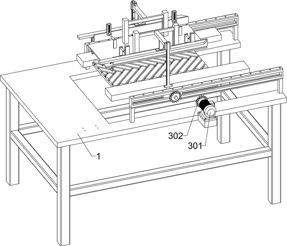
[0032] An automatic splicing glue injection fixing device for solid wood floors of automobiles, such as Figure 1-11 As shown, it includes chassis 1, conveying assembly, clamping assembly, sealing assembly and cutting assembly; the conveying assembly is installed on the left side of the upper side of the chassis 1; the clamping assembly is installed on the left side of the upper side of the chassis 1; the clamping assembly Located on the right side of the conveying assembly; a sealing assembly is installed on the upper side of the chassis 1; a cutting assembly is installed at the front and rear of the sealing assembly.

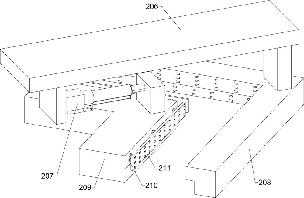
[0033] The conveying assembly includes a first fixed plate 101, a support plate 102, a first support frame 104, a second elastic telescopic rod 114, a V-shaped plate 115, a V-shaped receiving plate 116, a second wedge block 117 and a conveying unit; the chassis 1 A first fixed plate 101 is fixedly connected to the front side of the left part and the rear side ...

Embodiment 2

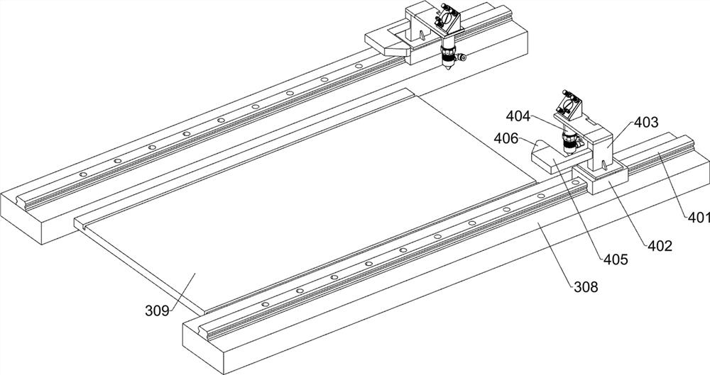
[0045] On the basis of Example 1, such as Figure 12 As shown, it also includes a glue injection assembly and a gantry 2; the upper left part of the bottom frame 1 is fixedly connected with the gantry 2; the upper part of the gantry 2 is installed with a glue injection assembly; the glue injection assembly includes a sixth fixing plate 501, Seventh fixed plate 502, third electric push rod 503, rubber delivery tube 504, electric rubber outlet head 505 and rubber guide tube 506; the sixth fixed plate 501 is fixed on the upper right side of the gantry frame 2; the sixth fixed plate 501 is fixed on the right side There is a seventh fixed plate 502; a third electric push rod 503 is fixedly connected to the lower front part and the lower rear part of the seventh fixed plate 502 respectively; Rubber hose 504; the upper part of the rubber hose 504 is fixed with two rubber guide tubes 506; the rubber guide tube 506 is connected with the rubber delivery tube 504; connected.

[0046] I...


PUM


Abstract

The invention relates to the field of automobile solid wood floors, in particular to automatic splicing, glue injecting and fixing equipment for automobile solid wood floors. The technical problems that when a groove is manually filled with a glue solution, the dosage of the glue solution is difficult to control accurately, excessive glue solution needs to be stricken off, the subsequent polishing difficulty is increased, and a large amount of glue solution is wasted are solved. According to the technical scheme, the automatic splicing, glue injecting and fixing equipment for the automobile solid wood floors comprises a bottom frame, a conveying assembly and the like; a conveying assembly used for conveying plastic plates is installed on the left portion of the upper side of the bottom frame. When the plastic plate splicing device is used, most of plastic plates are automatically spliced, limiting is conducted through a V-shaped bearing plate, deviation and dislocation of plastic plate splicing are avoided, the spliced plastic plates are fixed to a carrying plate, the spliced plastic plates are sealed after being cut, a groove is automatically filled with a glue solution by injecting the glue solution into a formed groove opening, the glue solution is prevented from being filled too much, and the quality of the plastic plates is improved. And meanwhile, resource waste is avoided, and the follow-up grinding difficulty is reduced.

Description

technical field [0001] The invention relates to the field of automobile solid wood floors, in particular to an automatic splicing glue injection fixing device for automobile solid wood floors. Background technique [0002] In the prior art, when producing solid wood flooring for automobiles, it is necessary to splice several plastic panels together obliquely. One side of the plastic panels is set as a convex structure, and the other side is set as a plane. After the plastic panels are spliced, the convex side faces upwards. After the plastic boards are merged, a groove is formed, and then the glue is filled into the groove manually, and the excess glue is scraped off. After curing, the excess part of the edge is cut off, and the surface of the plastic board is polished. Grind away the scraped glue traces and smooth the surface of the plastic board; the angle of inclination needs to be measured manually when splicing the plastic boards, and it is easy to shift and misalign du...

Claims


Application Information

Patent Timeline
Patent Type & Authority Applications(China)
IPC IPC(8): B27M3/04B27G11/00B27D1/10
Inventor 聂军基
Owner 伟源科技有限公司
Why Eureka
Try Eureka