Automatic batch assembling equipment for metal pen caps

A technology for assembling equipment and pen caps, which is applied to metal processing equipment, welding equipment, resistance welding equipment, etc., and can solve the problems of low quality of semi-finished pen caps, offset or even separation of shrapnel caps, and production of defective products, so as to avoid convex hull deviation. The effect of shifting dislocation, saving manpower and improving efficiency

Active Publication Date: 2022-06-28
NANJING TANG YI INFORMATION TECH CO LTD
View PDF7 Cites 0 Cited by
  • Summary
  • Abstract
  • Description
  • Claims
  • Application Information

AI Technical Summary

Problems solved by technology

[0004] In order to overcome the shortcoming that the shrapnel is easily shifted or even separated from the pen cap when using a spot welder for welding, resulting in defective products, and the same problem exists when welding convex bumps, which makes the quality of the semi-finished pen cap lower. The invention provides a metal pen cap. Automatic batch assembly equipment

Method used


Image

  • Automatic batch assembling equipment for metal pen caps
  • Automatic batch assembling equipment for metal pen caps
  • Automatic batch assembling equipment for metal pen caps

Examples


Embodiment 1

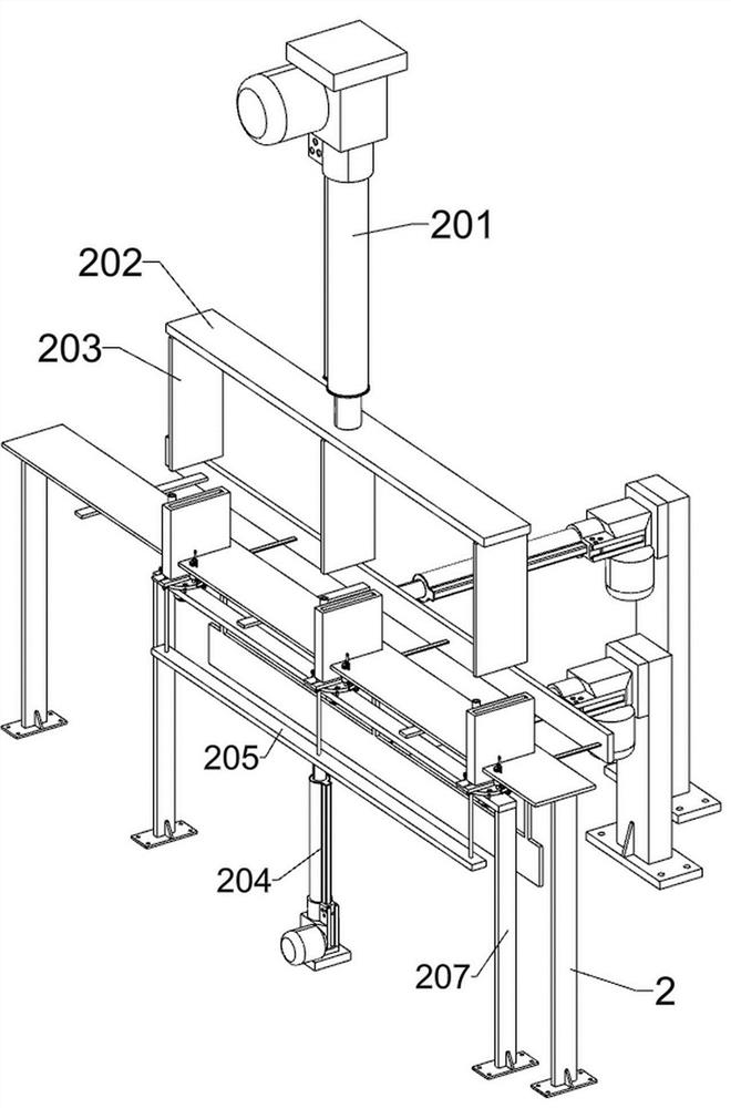
[0033] A metal pen cap automatic batch assembly equipment, such as Figure 1-11 As shown, it includes a base frame 1, a first support frame 2, a first fixing frame 3, a second fixing frame 4, an automatic spot welder 5, a collection box 6, a pen cover conveying assembly and an adhesive assembly; A first support frame 2 is fixedly connected to the right part of the side; a first fixing frame 3 is fixedly connected to the right part of the upper side of the bottom frame 1; Three equidistant second fixing frames 4 are connected; an automatic spot welding machine 5 is installed on the lower side of each second fixing frame 4; A pen cover conveying component is installed; an adhesive component is installed on the upper right part of the bottom frame 1 ; the adhesive component is connected with the first support frame 2 and the first fixing frame 3 .

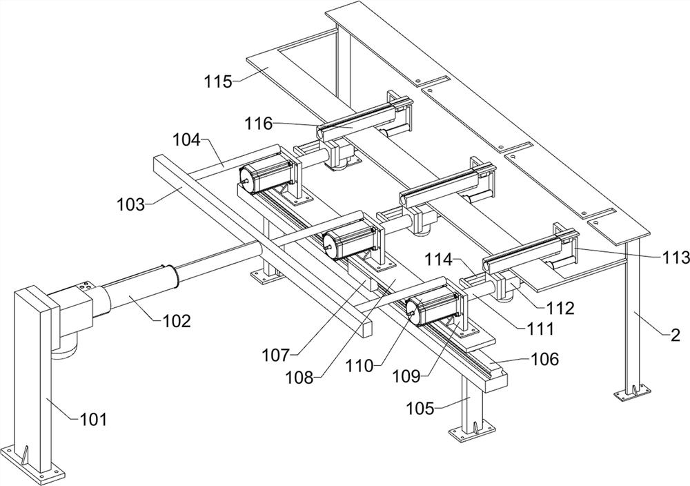
[0034] The pen cover conveying assembly includes a first support plate 101, a first electric push rod 102, a first fixing plate 103...

Embodiment 2

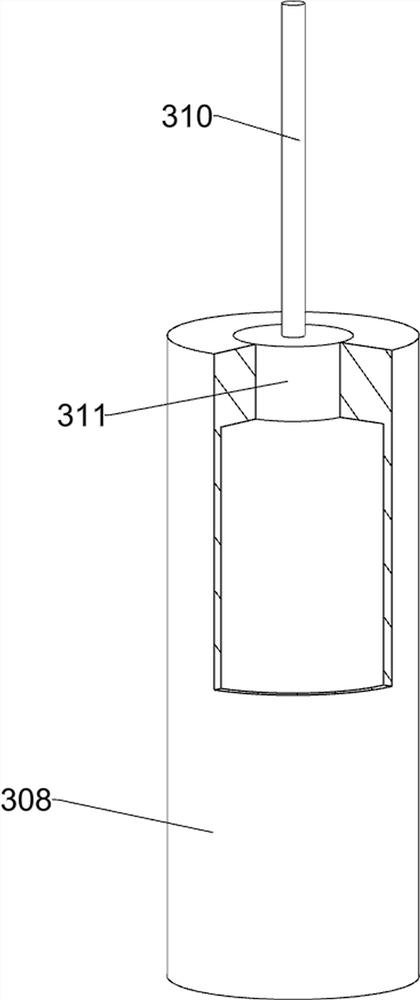
[0044] On the basis of Example 1, as Figure 12-14 As shown, it also includes a glue drop assembly; the upper part of the first fixing frame 3 is installed with a glue drop assembly; the glue drop assembly includes a U-shaped frame 301, a seventh electric push rod 302, an eighth fixing plate 303, and a fourth fixing frame 304 , the second glue liquid cylinder 305, the conduit 306, the second return spring 307, the glue dispensing head 308, the cross 309, the third fixing rod 310 and the second piston 311; the upper part of the first fixing frame 3 is fixed with a U-shaped frame 301; The seventh electric push rod 302 is fixedly connected to the lower side of the U-shaped frame 301; the telescopic end of the seventh electric push rod 302 is fixed to the eighth fixing plate 303; The lower part of the three fourth fixing frames 304 is fixed with a second glue liquid cylinder 305; the upper part of the three second glue liquid cylinders 305 is connected with a conduit 306; the lowe...


PUM


Abstract

The invention relates to the field of metal pen cap processing, in particular to automatic batch assembling equipment for metal pen caps. The technical problems are as follows: when a spot welding machine is used for welding, an elastic sheet is easy to deviate from or even separate from a pen cap to cause defective products, and when a convex hull is welded, the same problem exists to cause low quality of a pen cap semi-finished product. According to the technical scheme, the automatic batch assembling equipment for the metal pen caps comprises a bottom frame, a first supporting frame and the like; a first supporting frame is fixedly connected to the right portion of the upper side of the underframe. During use, a plurality of pen caps and elastic pieces are assembled at the same time, manual assembly is not needed, glue is dropped into pen cap mounting grooves, then the elastic pieces are inserted and bonded, the elastic pieces are prevented from deviating and separating from the pen caps during welding, it is guaranteed that the positions of the elastic pieces are not deviated after welding, the convex hulls are bonded to the elastic pieces by dispensing the glue on the convex hulls, and the welding efficiency is improved. Therefore, the quality of semi-finished pen caps is guaranteed, the efficiency is improved, and manpower is saved at the same time.

Description

technical field [0001] The invention relates to the field of metal pen cap processing, in particular to an automatic batch assembly equipment for metal pen caps. Background technique [0002] In the prior art, a metal pen cap is assembled and welded by a pen cover, a shrapnel and a convex hull, and a mounting groove for installing the shrapnel is milled out on the pen cover by a milling cutter. Then, the shrapnel is welded on the pen cap by a spot welding machine, and then the convex hull is placed at the designated position on the shrapnel, and the convex hull is welded on the shrapnel by a spot welding machine to obtain a semi-finished pen cap, and then follow-up Processing; due to the small size of the pen cover and the shrapnel, it is difficult to quickly insert the shrapnel into the installation slot on the pen cover during manual operation. When using a spot welding machine for welding, the shrapnel is easily offset or even separated from the pen cover, resulting in de...

Claims


Application Information

Patent Timeline
Patent Type & Authority Applications(China)
IPC IPC(8): B23K11/11B23K11/36B05C5/02B05C13/02
CPCB23K11/11B23K11/36B05C5/0212B05C5/027B05C13/02Y02P70/10
Inventor 朱根良
Owner NANJING TANG YI INFORMATION TECH CO LTD
Why Eureka
Try Eureka