Automatic milling machine equipment capable of automatically milling and polishing

An automatic milling machine and automatic milling technology, applied in metal processing equipment, other manufacturing equipment/tools, clamping and other directions, can solve the problems of inability to separate scrap iron filings, inability to fix raw materials of different shapes, and inaccessibility, and to improve The effect of quality of work

Pending Publication Date: 2022-04-08
王夫其
View PDF0 Cites 1 Cited by
  • Summary
  • Abstract
  • Description
  • Claims
  • Application Information

AI Technical Summary

Problems solved by technology

[0002] Milling is a common technical means for metal processing. In order to speed up milling, automatic milling machine equipment for milling has appeared, but the existing automatic milling machine equipment cannot fix raw materials of different shapes well. In addition, the existing automatic milling machine equipment The milling machine equipment can not separate the cutting fluid and the milling waste iron chips well, it is not convenient for the recycling of the cutting fluid and the centralized collection and treatment of the scrap iron chips, and it cannot meet the requirements of the existing technology, so we propose An automatic milling machine equipment for automatic milling and grinding

Method used


Image

  • Automatic milling machine equipment capable of automatically milling and polishing
  • Automatic milling machine equipment capable of automatically milling and polishing
  • Automatic milling machine equipment capable of automatically milling and polishing

Examples


Embodiment Construction

[0030] The following will clearly and completely describe the technical solutions in the embodiments of the present invention with reference to the accompanying drawings in the embodiments of the present invention. Obviously, the described implementation regulations are only some, not all, embodiments of the present invention.

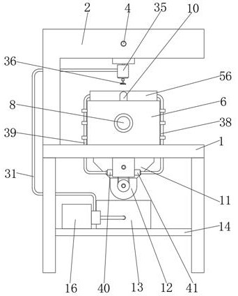
[0031] see Figure 1 to Figure 11 , the present invention provides a technical solution: an automatic milling machine equipment for automatic milling and grinding, comprising a milling platform 1, a first transmission belt 23, and a second transmission belt 30, the two ends of the top surface of the milling platform 1 are provided with a fixed base plate 6, The middle part of the milling platform 1 is provided with a sliding cylinder 11, the inside of the fixed base plate 6 is provided with a moving groove 7, the top surface of the fixed base plate 6 is provided with an avoidance groove 9, and the end face of the fixed base plate 6 is fixedly installed ...


PUM


Abstract

The invention discloses automatic milling and polishing automatic milling machine equipment, and relates to the technical field of automatic milling machines, the automatic milling machine equipment comprises a milling platform, a first transmission belt and a second transmission belt, fixed base plates are arranged at the two ends of the top surface of the milling platform, a sliding cylinder is arranged in the middle of the milling platform, and moving grooves are formed in the fixed base plates; a receding groove is formed in the top face of the fixed base plate. According to the automatic milling machine equipment with the automatic milling and grinding functions, a filter cylinder, a spiral conveying rod and a filter hole are used in cooperation, when milling waste enters an inner cavity of the filter cylinder from a sliding cylinder, cutting fluid in scrap iron flows back to an inner cavity of a cutting fluid box from the filter hole, and the function of automatically separating the scrap iron from the cutting fluid is achieved; and in addition, the filtered scrap iron is driven by the rotating spiral conveying rod to move forwards, so that the scrap iron falls into an inner cavity of the collecting box from one end of the filter cartridge, and the function of collecting the scrap iron is achieved.

Description

technical field [0001] The invention relates to the technical field of automatic milling machines, in particular to automatic milling machine equipment for automatic milling and grinding. Background technique [0002] Milling is a common technical means for metal processing. In order to speed up milling, automatic milling machine equipment for milling has appeared, but the existing automatic milling machine equipment cannot fix raw materials of different shapes well. In addition, the existing automatic milling machine equipment The milling machine equipment cannot separate the cutting fluid from the milling waste iron chips well, which is not convenient for the recycling of cutting fluid and the centralized collection and treatment of scrap iron chips, which cannot meet the requirements of the existing technology. Therefore, we propose An automatic milling machine equipment for automatic milling and grinding. Contents of the invention [0003] Aiming at the deficiencies o...

Claims


Application Information

Patent Timeline
IPC IPC(8): B23Q3/08B23Q11/00B23Q11/10B23P23/04
Inventor 王夫其
Owner 王夫其
Why Eureka
Try Eureka