Evaporative atomizer for sterilizing germs

An evaporative and atomizer technology, applied in the field of atomizers, can solve the problems of waste, affecting the sterilization effect, poor use effect, etc., and achieve good effect and good effect of mist discharge

Pending Publication Date: 2022-04-08
SHENZHEN YONGHENGFENG INTELLIGENT DEVICE
View PDF0 Cites 0 Cited by
  • Summary
  • Abstract
  • Description
  • Claims
  • Application Information

AI Technical Summary

Problems solved by technology

[0003] Most of the existing evaporative atomizers for disinfecting germs use a fan to blow out the atomized disinfectant through the guide tube, so as to disinfect the germs in the external environment, but the temperature of the guide tube body is low, and the fan It also directs the gas from the outside air into the guide tube to blow out the atomized gas. When the gas that has just been atomized at high temperature is cold, it is easy to form water droplets and adhere to the wall of the guide tube, and it will return to the atomization barrel again, which will cause Only half of the atomizing gas is blown out through the guide tube, and the use effect is not good
[0004] The existing evaporative nebulizers for killing germs are used to pour all the sterilizing liquid into the atomizing barrel. Since the sterilizing liquid is prepared from various liquids, the evaporative atomizer is used directly without sufficient mixing. The atomization of the device will affect the sterilization effect
[0005] The existing evaporative nebulizers for killing germs are used to pour all the sterilizing liquid into the atomizing barrel, and use the evaporator to continuously atomize the sterilizing liquid, but this kind of nebulizer cannot control the concentration of the atomized gas. Concentration, when sterilizing a small area of ​​space, it will cause waste

Method used


Image

  • Evaporative atomizer for sterilizing germs
  • Evaporative atomizer for sterilizing germs
  • Evaporative atomizer for sterilizing germs

Examples


Embodiment Construction

[0029] The following will clearly and completely describe the technical solutions in the embodiments of the present invention with reference to the accompanying drawings in the embodiments of the present invention. Obviously, the described embodiments are only some, not all, embodiments of the present invention. Based on the embodiments of the present invention, all other embodiments obtained by persons of ordinary skill in the art without making creative efforts belong to the protection scope of the present invention.

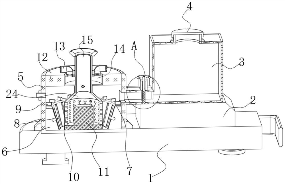
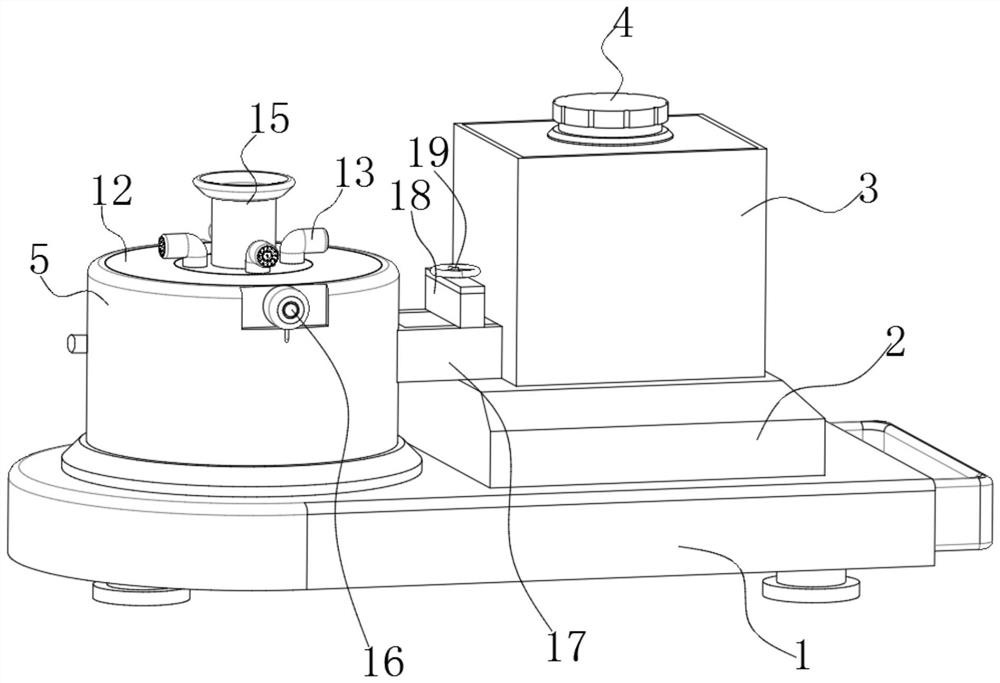
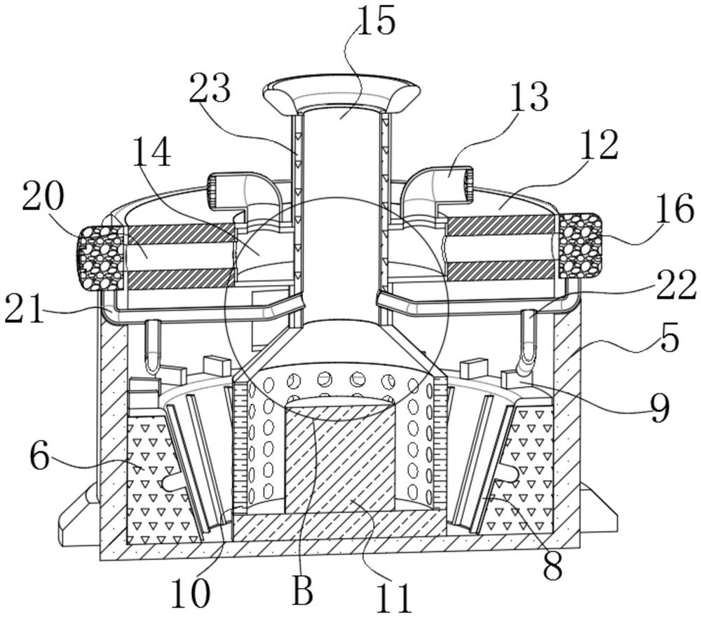
[0030] like Figure 1 to Figure 8As shown, in the embodiment of the present invention, an evaporative atomizer for killing germs includes a base 1 and a fan 16. An atomization barrel 5 is fixedly installed on the top of the left end of the base 1, and the interior of the upper end of the atomization barrel 5 is fixedly connected to There is a top plate 12, an evaporator 11 is fixedly installed on the bottom of the atomization barrel 5, a protective cover 10 is...


PUM


Abstract

The invention belongs to the technical field of atomizers, and discloses an evaporative atomizer for sterilizing germs.The evaporative atomizer comprises a base and a fan, an atomizing barrel is fixedly mounted at the top of the left end of the base, a top plate is fixedly connected to the interior of the upper end of the atomizing barrel, and an evaporator is fixedly mounted at the bottom of the interior of the atomizing barrel; a protective cover is fixedly connected to the top of the outer side of the lower end of the evaporator, and a gas collecting cover is fixedly installed at the top of the protective cover. Through cooperation of the hot air chamber, the air guiding channel, the air distributing pipe and other structures, the mist exhausting effect is good, liquid is vaporized into mist through high temperature through work of the evaporator, the mist is directly guided into the guiding pipe through the air collecting hood, meanwhile, a heating piece is powered on to generate heat, hot air entering the hot air chamber can be heated, and the heat efficiency is improved. And the fans at the two ends work to guide hot air in the hot air chamber into the air guide pipes at the two ends through the air guide channels at the two ends, so that the aim of good mist exhaust effect can be achieved.

Description

technical field [0001] The invention belongs to the technical field of atomizers, in particular to an evaporative atomizer for disinfecting germs. Background technique [0002] The evaporative atomizer for germ killing refers to the use of high-temperature heating of the evaporator to provide the heat required for evaporation to the sterilizing liquid, so that the sterilizing liquid is boiled and vaporized, and then the atomized gas is exported through the guide tube, so as to facilitate the surrounding environment. Sterilize. [0003] Most of the existing evaporative atomizers for disinfecting germs use a fan to blow out the atomized disinfectant through the guide tube, so as to disinfect the germs in the external environment, but the temperature of the guide tube body is low, and the fan It also directs the gas from the outside air into the guide tube to blow out the atomized gas. When the gas that has just been atomized at high temperature is cold, it is easy to form wate...

Claims


Application Information

Patent Timeline
Patent Type & Authority Applications(China)
IPC IPC(8): A61L2/22A61L2/26A61L9/14B05B15/25B05B12/08B05B15/55
Inventor 刘志国刘志刚陈深旺
Owner SHENZHEN YONGHENGFENG INTELLIGENT DEVICE
Why Eureka
Try Eureka