
Electromagnetic sealing structure for photoelectric pod rotating shaft system

A technology of photoelectric pods and rotating shafts, applied in the direction of electrical components, magnetic field/electric field shielding, etc., can solve the problems of internal equipment radiation that cannot be quickly and effectively solved, low efficiency, complex shielding package processing methods, etc., to solve electromagnetic leakage problems, Reduce difficulty and complexity, reduce the effect of electromagnetic radiation leakage

Pending Publication Date: 2022-04-05
LUOYANG INST OF ELECTRO OPTICAL EQUIP OF AVIC
View PDF0 Cites 0 Cited by
  • Summary
  • Abstract
  • Description
  • Claims
  • Application Information

AI Technical Summary

Problems solved by technology

[0003] At present, the commonly used design method is to process the internal equipment of the photoelectric pod, and increase shielding protection for equipment or components with electromagnetic radiation, especially for equipment and cables with large electromagnetic radiation. Overall leakage, this method needs to repeatedly wrap and shield the equipment and then conduct tests. At the same time, due to the irregular shape of the equipment, the shielding and wrapping treatment method is complicated, and the radiation of the internal equipment cannot be quickly and effectively solved. It is necessary to repeat the shielding treatment test many times. less efficient

Method used


Image

  • Electromagnetic sealing structure for photoelectric pod rotating shaft system
  • Electromagnetic sealing structure for photoelectric pod rotating shaft system
  • Electromagnetic sealing structure for photoelectric pod rotating shaft system

Examples


Embodiment Construction

[0028] The embodiments described below by referring to the figures are exemplary and are intended to explain the present invention and should not be construed as limiting the present invention.

[0029] In describing the present invention, it should be understood that the terms "center", "longitudinal", "transverse", "length", "width", "thickness", "upper", "lower", "front", " Orientation indicated by rear, left, right, vertical, horizontal, top, bottom, inside, outside, clockwise, counterclockwise, etc. The positional relationship is based on the orientation or positional relationship shown in the drawings, which is only for the convenience of describing the present invention and simplifying the description, rather than indicating or implying that the referred device or element must have a specific orientation, be constructed and operated in a specific orientation, Therefore, it should not be construed as limiting the invention.

[0030] An electromagnetic sealing structure ...


PUM


Abstract

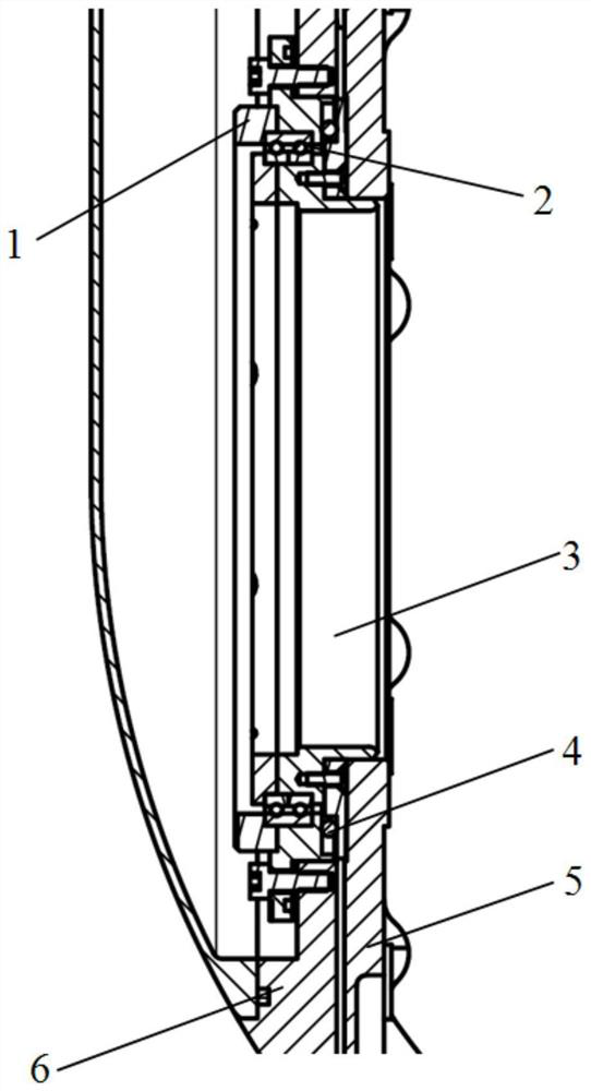
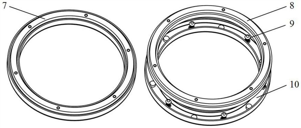
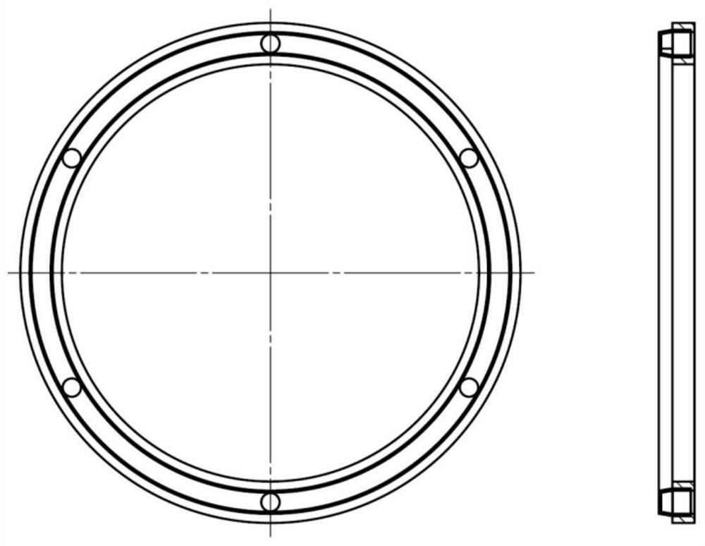
The invention discloses a structure for electromagnetic sealing of a rotating shaft system of a photoelectric pod, and belongs to the technical field of airborne photoelectricity. Comprising a fixed conductive seat, a conductive brush and an automatic pre-tightening device, the fixed conductive seat is fixed on a shafting fixing shell, and the conductive brush is fixed on a shafting rotating shell; a notch of the conductive brush and a notch of the fixed conductive seat are oppositely arranged, and the conductive brush is coaxially inserted into a U-shaped ring groove of the fixed conductive seat; the multiple automatic pre-tightening devices are arranged between the fixed conductive base and the conductive brush in the circumferential direction. A fixed seat of the automatic pre-tightening device is fixed on the inner bottom surface of a U-shaped groove of a fixed conductive seat, and a spherical contact head is always in close contact with a conductive brush through elastic force pre-tightening of a spring. The fixed conductive seat and the conductive brush are in close contact all the time under the action of the automatic pre-tightening device, contact rotation is kept in the shafting rotating motion process, all-metal conductive shielding of the rotating part of the photoelectric pod in the moving or static state is achieved, and an electromagnetic interference source of equipment in the photoelectric pod is effectively shielded.

Description

technical field [0001] The invention belongs to the technical field of airborne optoelectronics, and in particular relates to an electromagnetic sealing structure for a rotating shaft system of an optoelectronic pod. Background technique [0002] The airborne photoelectric pod is a photoelectric device installed on a drone, helicopter or fixed-wing aircraft for observation, search and mapping. The rotating shaft is a necessary part for the movement of the photoelectric pod. The bearing and The selection of non-metallic sealing ring is essential. The gap between the inner ring, outer ring and rolling elements of the bearing and the part of the non-metallic sealing ring are the spaces that cause the leakage of electromagnetic radiation of the photoelectric pod. The treatment of the rotating shaft system in the electro-optical pod electromagnetic compatibility test has always been a troublesome part. [0003] At present, the commonly used design method is to process the intern...

Claims


Application Information

Patent Timeline
IPC IPC(8): H05K9/00
Inventor 戚立强秦晓科蔡婷婷梁璐张世浩
Owner LUOYANG INST OF ELECTRO OPTICAL EQUIP OF AVIC
Learn More