
Wireless charging device

A wireless charging and charger technology, applied in circuit devices, battery circuit devices, current collectors, etc., can solve the problems of high requirements for charger control switches and auxiliary circuits, large electromagnetic radiation, low charging efficiency, etc. Efficiency of wireless charging, cost reduction, effect of reducing electromagnetic radiation

Inactive Publication Date: 2013-07-24
SHENZHEN INTON TECH
View PDF6 Cites 0 Cited by
  • Summary
  • Abstract
  • Description
  • Claims
  • Application Information

AI Technical Summary

Problems solved by technology

[0003] 1. Large electromagnetic radiation;
[0004] 2. Low charging efficiency;
[0005] 3. The current is large during transmission, which has high requirements for the control switch and auxiliary circuit of the charger

Method used

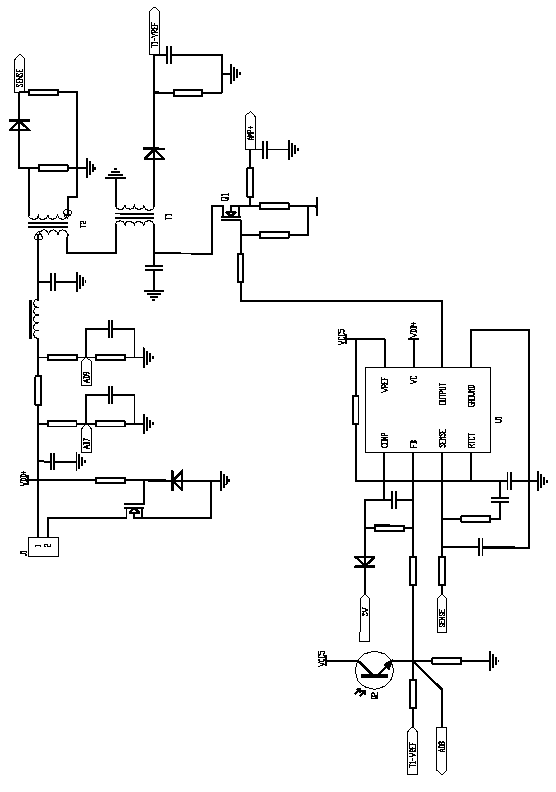
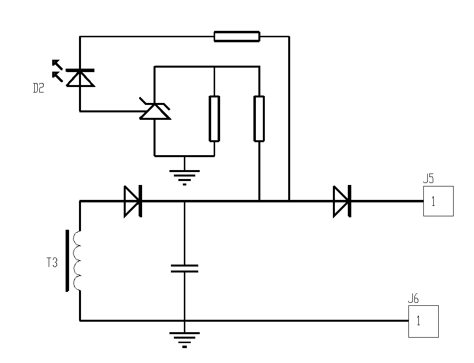

Image

  • Wireless charging device
  • Wireless charging device

Examples


Embodiment Construction

[0017] First, the basis of the invention is explained:

[0018] (1) Charging principle

[0019] The two incomplete magnetic cores used for transmitting and receiving respectively need to be close together, preferably aligned, to form a complete magnetic flux circuit. During normal operation, the transmitting coil transmits energy to the receiving coil through this complete magnetic flux circuit to achieve the purpose of charging;

[0020] (2) The principle of automatic charging

[0021] You can choose the following two ways:

[0022] 1. Detect whether an object is approaching by infrared; and / or

[0023] 2. By reading the voltage of the feedback coil, whether a complete magnetic core circuit and receiving coil are formed;

[0024] Ⅲ charging protection principle

[0025] You can choose the following two ways:

[0026] 1. By reading the voltage of the feedback coil, it can be judged whether the battery in the device being charged is fully charged, so as to disconnect the ...


PUM


Abstract

The invention relates to a wireless charging device, which comprises a charger and an electricity consumption appliance, wherein a transmitting coil is arranged in the charger; a receiving coil is arranged in the electricity consumption appliance; the transmitting coil and the receiving coil are provided with own magnetic cores; and the two magnetic cores abut against each other to form an internal closed magnetic-flux loop in a charging state. The wireless charging device greatly reduces external electromagnetic radiation, improves charging efficiency, has a simple circuit, is low in cost, and can realize automatic charging and charging protection in combination with a feedback coil and infrared detection control.

Description

technical field [0001] The invention relates to charging of electronic products, in particular to a green, environment-friendly, low-radiation and high-efficiency wireless charging device. Background technique [0002] Wireless charging devices do not require metal contact points, which greatly facilitates the use of users, and are increasingly popularized and accepted. At present, the existing wireless charging device adopts a coreless coil or a strip magnetic core coil, which belongs to an open magnetic field. When charging, on the one hand, the transmitting coil emits a large amount of electromagnetic waves; on the other hand, the receiving coil receives part of the electromagnetic waves and converts them into electrical energy, so the charging efficiency is low; at the same time, IC induction is used to realize automatic charging, and the structure is relatively complicated. Generally speaking, prior art has following shortcoming: [0003] 1. Large electromagnetic radi...

Claims


Application Information

Patent Timeline
Patent Type & Authority Patents(China)
IPC IPC(8): H02J7/02H02J17/00H02J50/10
Inventor 赖益嵩张鹏
Owner SHENZHEN INTON TECH
Learn More