Outer rotor structure of brushless motor and surface treatment method thereof

A brushless motor and surface treatment technology, applied in chemical instruments and methods, manufacturing stator/rotor body, magnetic circuit shape/style/structure, etc., can solve problems such as poor stability, poor motion stability, and large structural imbalance. Achieve the effect of reducing the difficulty of assembly and ensuring stability

Active Publication Date: 2022-04-05
ZHEJIANG ZHONGLI TOOL MFG
View PDF6 Cites 0 Cited by
  • Summary
  • Abstract
  • Description
  • Claims
  • Application Information

AI Technical Summary

Problems solved by technology

[0006]In order to solve the poor structural stability of the existing brushless motor outer rotor, due to its complicated structural components, it is easy to produce different degrees of misalignment during the assembly process, resulting in uneven structure The weight is large, and it is easy to cause problems such as poor motion stability due to material factors during actual use. The invention provides a brushless motor outer rotor structure and a method for further surface treatment

Method used


Image

  • Outer rotor structure of brushless motor and surface treatment method thereof
  • Outer rotor structure of brushless motor and surface treatment method thereof
  • Outer rotor structure of brushless motor and surface treatment method thereof

Examples


Embodiment

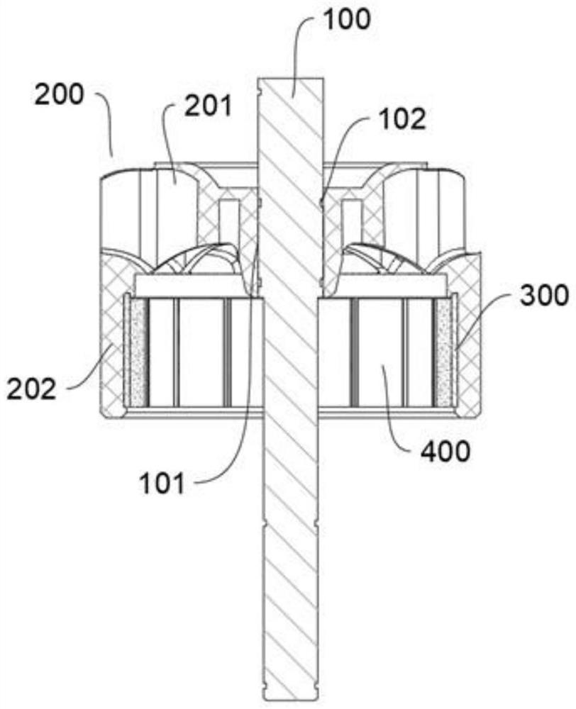
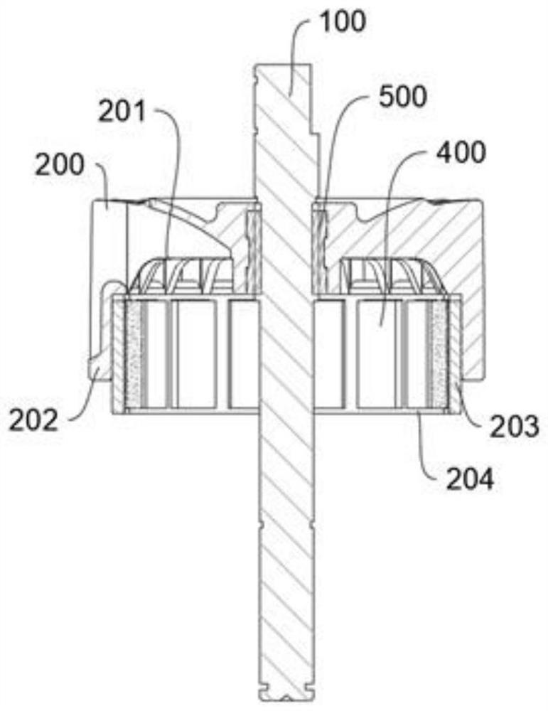
[0060] a kind of like figure 1 The outer rotor structure of the brushless motor shown specifically includes:

[0061] Rotor shaft 100, impeller 200 and magnetic structure;

[0062] The impeller 200 is sleeved on the rotor shaft 100, and the rotor shaft 100 is provided with an anti-slip structure relative to the place where the impeller 200 is sleeved;

[0063] The anti-slip structure specifically includes a radial anti-slip structure that prevents the impeller 200 from slipping in the circumferential direction relative to the rotor shaft 100, and an axial anti-slip structure that prevents the impeller 200 from slipping axially relative to the rotor shaft 100;

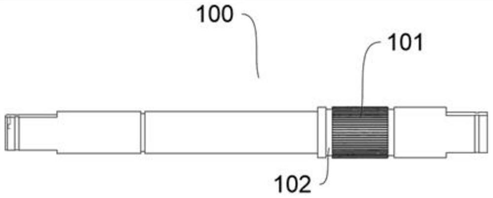
[0064] Specific as image 3 shown;

[0065] The radial anti-slip structure includes, but is not limited to, conventional anti-slip structures such as knurling or damping treatment on the outer surface to form a damping layer or snap fit and fixation, but for the present invention, this embodiment adopts a relatively ...


PUM

PropertyMeasurementUnit
Tensile strengthaaaaaaaaaa

Abstract

The invention belongs to the field of brushless motors, and particularly relates to a brushless motor outer rotor structure and a surface treatment method thereof. The rotor comprises a rotor shaft, an impeller and a magnetomotive structure, the impeller is arranged on the rotor shaft in a sleeving mode, and an anti-skid structure is arranged at the joint of the impeller and the rotor shaft. The anti-skid structure comprises a radial anti-skid structure and an axial anti-skid structure; the impeller comprises fan blades and a sleeve formed by extending in the axial direction of the rotor shaft. The magnetomotive structure comprises a magnet yoke and a magnetic shoe; the magnet yoke is provided with a clamping groove used for assembling the magnetic shoe, and the magnet yoke is fixedly arranged in the sleeve. The magnet yoke is of an annular structure and is matched with the inner wall of the sleeve in an anti-skid mode. Through the reasonable structural design, the assembling difficulty of the whole outer rotor structure is greatly reduced, the concentricity of the impeller, the rotor shaft, the magnet yoke and other structures can be effectively improved while the stability of the whole structure is ensured, and meanwhile the materials of the impeller, the rotor shaft, the magnet yoke and other components are reasonably adjusted and improved.

Description

technical field [0001] The invention belongs to the field of brushless motors, in particular to an outer rotor structure of a brushless motor and a surface treatment method thereof. Background technique [0002] The brushless motor is a typical mechatronic product, and the outer rotor brushless motor is a typical brushless motor with an outer rotor structure. Compared with the inner rotor brushless motor of the same size, the outer rotor brushless motor has the advantages of large torque, large moment of inertia, easier heat dissipation, and greater flatness ratio. More and more products that require high torque and high speed use the external rotor direct motor. Drive motors, such as drones, model airplanes, electric chain saws, lawn trimmers, etc. [0003] The rotor shaft of the low-power external rotor brushless motor and the motor yoke (steel ring sleeve) are generally combined by press-fitting or stamping with interference fit or bonding with glue. The yoke of the out...

Claims


Application Information

Patent Timeline
Patent Type & Authority Applications(China)
IPC IPC(8): H02K1/2791H02K1/28C09K5/06H02K15/03
Inventor 朱连兵赵伟忠徐建锋李燕冯仁超
Owner ZHEJIANG ZHONGLI TOOL MFG
Why Eureka
Try Eureka