Kinetic energy interceptor based on head deflection

A kinetic energy interceptor and head technology, which is applied in the field of kinetic energy interceptors based on head deflection, can solve problems such as poor hit accuracy and large hit deviation of low-altitude targets, so as to reduce hit error, improve hit accuracy, and increase collision area Effect

Pending Publication Date: 2022-04-05
AEROSPACE SCI & IND MICROELECTRONICS SYST INST CO LTD
View PDF0 Cites 0 Cited by
  • Summary
  • Abstract
  • Description
  • Claims
  • Application Information

AI Technical Summary

Problems solved by technology

[0009] Aiming at the disadvantages of the existing kinetic energy interceptors, such as the poor hitting accuracy and large deviation of low-altitude targets, the present invention designs a kinetic energy interceptor that relies on head deflection to provide lateral overload

Method used


Image

  • Kinetic energy interceptor based on head deflection
  • Kinetic energy interceptor based on head deflection
  • Kinetic energy interceptor based on head deflection

Examples


Embodiment Construction

[0033] The solution of the present invention will be described in detail below in conjunction with the accompanying drawings.

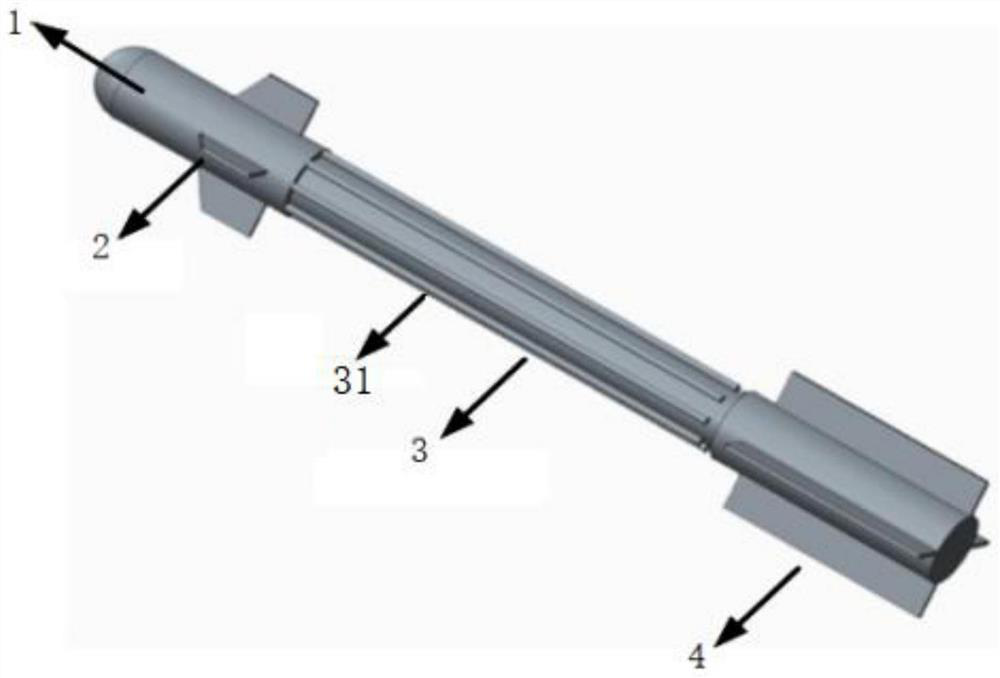
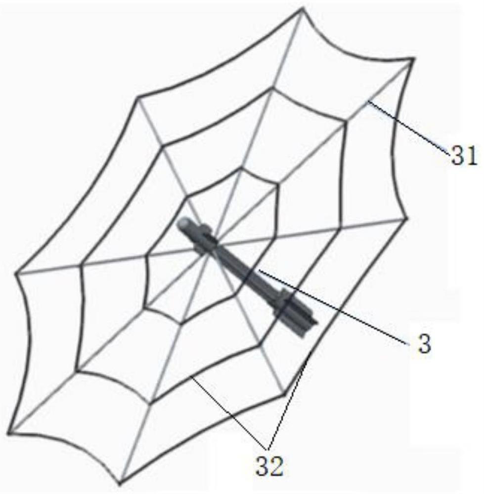
[0034] A kinetic energy interceptor based on head deflection, such as figure 1 As shown, from front to back, it includes the guidance cabin, the instrument cabin, the kinetic energy combat cabin and the tail section in series. The integrated control machine and battery are installed inside the nose cone cabin, and the electrical single machines installed in the cabin section are connected to the battery through power supply cables. , transmit data information through the control cable;

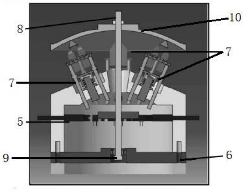
[0035] The head deflection mechanism is installed at the rear end of the guidance cabin, and the rudder control module of the integrated integrated control machine sends deflection commands, which are transmitted to the head deflection mechanism through the control cable. The head deflection mechanism deflects in the pitch and yaw directions according to the command, ...


PUM


Abstract

The invention relates to a kinetic energy interceptor based on head deflection. In order to overcome the defects that an existing kinetic energy interceptor is poor in hit precision and large in hit deviation for a low-altitude target, the kinetic energy interceptor providing lateral overload by means of head deflection is designed and sequentially comprises a guide cabin, an instrument cabin, a kinetic energy combat cabin and a tail section which are connected in series from front to back, and an integrated comprehensive control machine and a battery are installed in a head cone cabin. Each electrical single machine arranged in the cabin section is connected with a battery through a power supply cable, and data information is transmitted through a control cable; a head deflection mechanism is installed at the rear end of the guide cabin, the integrated comprehensive control machine rudder control module sends a deflection instruction, and the head deflection mechanism deflects in the pitching direction and the yawing direction according to the instruction and provides lateral pneumatic capacity; the kinetic-energy combat cabin is connected with the instrument cabin through a center main shaft, an electric thrust rod is installed in the center main shaft, a kinetic-energy intercepting folding rod is installed outside the center main shaft, a three-section folding mode is adopted, and the folding rod is placed on the surface of the projectile body after being folded.

Description

technical field [0001] The invention relates to the technical field of missile defense, in particular to a kinetic energy interceptor based on head deflection. Background technique [0002] The kinetic energy interceptor is a combat weapon derived from the development of rocket weapons. With the development of precision-guided weapon technology, intercepting enemy targets can also choose to use kinetic energy to intercept and directly hit the target, causing damage to the structure and performance of the enemy target, or the posture becomes unstable and the battle cannot continue. [0003] At present, the main power mode for kinetic energy interceptors is direct force or direct / air compound mode. The main weakness of the existing technology is that the hit accuracy is poor. For low-altitude targets, the hit deviation is relatively large. The hit accuracy error mainly comes from four aspects: [0004] Launching devices, traditional artillery and missile launches, due to the...

Claims


Application Information

Patent Timeline
Patent Type & Authority Applications(China)
IPC IPC(8): F41H11/02
Inventor 武春风周啟帆秦建飞王盛龙齐柏一秦勇谢峰白明顺
Owner AEROSPACE SCI & IND MICROELECTRONICS SYST INST CO LTD
Why Eureka
Try Eureka