
Patsnap Eureka
For R&D, Patsnap Eureka makes reading and utilizing patents & technical documents easy.
Patsnap Eureka AIR
Designed for self-driven R&D workflows. Generate viable solutions, solve complex R&D challenges, empower your innovation with AI.

Patsnap Eureka Materials
Designed for material experts only. Revolutionize your material R&D, from search, analyze, to developing new materials.

TechResearch
Generate reliable direction feasibility study reports for your R&D in just a few steps.

TechSeek
Discover and master advanced knowledge NOW. Basics, ideas, possibilities, all at once.

TechMind
As an expert in R&D Theories, TechMind can generates customized viable solutions instantly.

TechRisk
Analyze your overall solution with one click, know your potential R&D risks in advance.

TechMonitor
Get weekly tech updates, stay abreast of the latest tech innovations and key insights.
Hole bridge cooling channel
A cooling channel and coolant jacket technology, which is applied in liquid cooling, engine cooling, coolant flow control, etc., can solve the problems of complex, expensive, and insufficient cooling in the cooling system, so as to avoid deformation of the cylinder bore and increase the surface area Effect
- Summary
- Abstract
- Description
- Claims
- Application Information
AI Technical Summary
Problems solved by technology
Method used
Image

Examples
Embodiment Construction
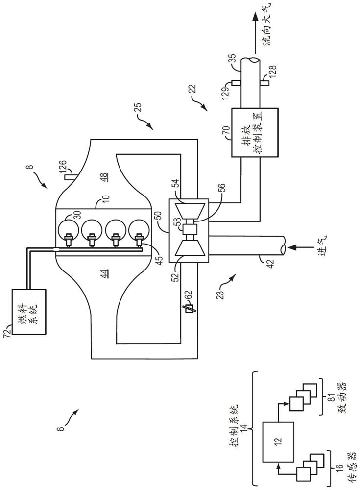
[0021] figure 1 A schematic diagram of a vehicle system 6 is shown. Vehicle system 6 includes engine system 8 coupled to exhaust aftertreatment system 22 . Engine system 8 may include engine 10 having a plurality of cylinders 30 . Engine 10 includes an engine intake 23 and an engine exhaust 25 . Engine intake 23 includes throttle 62 fluidly coupled to engine intake manifold 44 via intake passage 42 . The engine exhaust 25 includes an exhaust manifold 48 that ultimately leads to an exhaust passage 35 that directs exhaust gas to the atmosphere. Throttle 62 may be located downstream of a boosting device, such as turbocharger 50 or a supercharger, in intake passage 42 .
[0022] Turbocharger 50 may include a compressor 52 disposed between intake passage 42 and intake manifold 44 . Compressor 52 may be at least partially powered by exhaust turbine 54 disposed between exhaust manifold 48 and exhaust passage 35 . Compressor 52 may be coupled to exhaust turbine 54 via shaft 56 ....
PUM
 Abstract
Description
Claims
Application Information
 - R&D Engineer
- R&D Manager
- IP Professional
- Industry Leading Data Capabilities
- Powerful AI technology
- Patent DNA Extraction
Browse by: Latest US Patents, China's latest patents, Technical Efficacy Thesaurus, Application Domain, Technology Topic, Popular Technical Reports.
© 2024 PatSnap. All rights reserved.Legal|Privacy policy|Modern Slavery Act Transparency Statement|Sitemap|About US| Contact US: help@patsnap.com