


Quick Research
Generate reliable direction feasibility study reports for your R&D in just a few steps.

Technical Q&A
Discover and master advanced knowledge NOW. Basics, ideas, possibilities, all at once.

Find Solutions
As an expert in R&D theories, this can generate solutions to your technical problems instantly.

Evaluate Feasibility
Analyze your overall solution with one click, know your potential R&D risks in advance.

Monitor Landscape
Get weekly tech updates, stay abreast of the latest tech innovations and key insights.
Continuous casting and rolling production line capable of avoiding ferrite rolling mixed crystal and production method
A continuous casting and rolling, ferrite technology, applied in the direction of metal rolling, metal rolling, manufacturing tools, etc., can solve the problems of deteriorating the microstructure and properties of the finished strip, short transformation time, mixed crystals, etc., and improve the microstructure. The uniformity of performance, the effect of increasing the added value of products and expanding the scope of application
- Summary
- Abstract
- Description
- Claims
- Application Information
AI Technical Summary
Problems solved by technology
Method used
Image

Examples
Embodiment 1
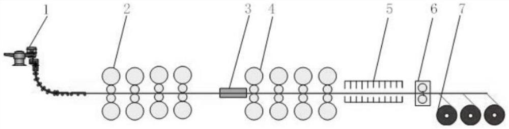
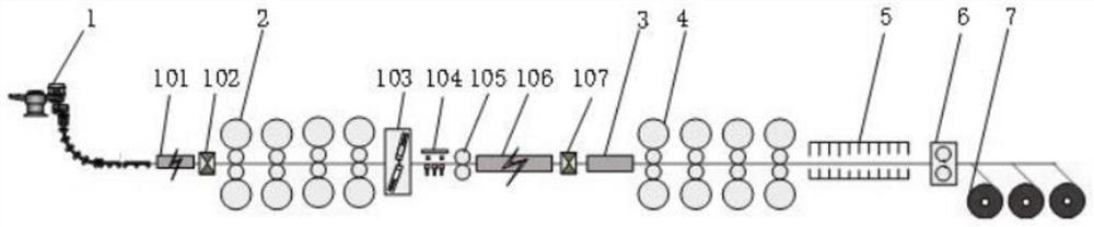
[0030] see figure 2 , the continuous casting and rolling production line in this embodiment includes a continuous casting machine 1, a roller hearth tunnel furnace 101, a high-pressure water descaling box 102, a rough rolling unit 2, a pendulum shear 103, and a waste pushing device arranged in sequence along the rolling direction 104. Accident shear with looper 105, induction heating device 106, high-pressure water descaling box 107, intermediate blank heat preservation device 3, finishing rolling unit 4, post-rolling cooling device 5, high-speed flying shear 6 and coiling unit 7; , the intermediate billet heat preservation device can adopt a gas protection heating furnace or a vacuum heating furnace. In this embodiment, a nitrogen protection heating furnace is selected, and the length of the furnace body is selected as 15m, which can make the intermediate billet in the furnace heat preservation or slow cooling for more than 5s, and avoid the intermediate billet Surface oxida...
Embodiment 2
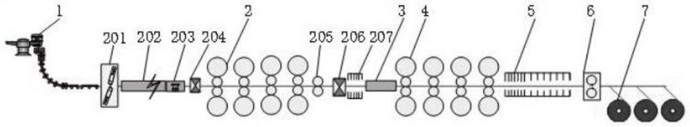
[0037] see image 3 , the continuous casting and rolling production line in this embodiment includes a continuous casting machine 1, a pendulum shear 201, a roller hearth tunnel furnace 202, a high-pressure water descaling box 204, a rough rolling unit 2, and a drum shear that are arranged in sequence along the rolling direction. 205, high-pressure water descaling box 206, rapid cooling device 207, intermediate billet heat preservation device 3, finishing rolling unit 4, post-rolling cooling device 5, high-speed flying shear 6 and coiling unit 7. The roller hearth tunnel furnace 202 also includes a laterally movable slab pushing unit 203 . Intermediate billet heat preservation device 3 In this embodiment, a nitrogen-protected heating furnace is selected, and the length of the furnace body is selected as 15 m, which can keep the intermediate billet in the furnace for more than 5 seconds and avoid surface oxidation of the intermediate billet. The rough rolling unit 2 includes 2...
Embodiment 3
[0042] see Figure 4 , the continuous casting and rolling production line in this embodiment includes a continuous casting machine 1, a high-pressure water descaling box 301, a rough rolling unit 2, a pendulum shear 302, a waste pushing device 303, an induction heating device 304, High-pressure water descaling box 305, rough rolling unit 2, induction heating device 306, accident shear with looper 307, high-pressure water descaling box 308, intermediate billet heat preservation device 3, finishing rolling unit 4, post-rolling cooling device 5, high-speed Flying shear 6 and coiling unit 7. Intermediate billet heat preservation device 3 In this embodiment, a nitrogen-protected heating furnace is selected, and the length of the furnace body is selected as 15 m, which can keep the intermediate billet in the furnace for more than 5 seconds and avoid surface oxidation of the intermediate billet. The rough rolling unit 2 includes 2 to 6 rough rolling stands, 4 stands are selected in ...
PUM
 Abstract
Description
Claims
Application Information
 - R&D Engineer
- R&D Manager
- IP Professional
- Industry Leading Data Capabilities
- Powerful AI technology
- Patent DNA Extraction
Browse by: Latest US Patents, China's latest patents, Technical Efficacy Thesaurus, Application Domain, Technology Topic, Popular Technical Reports.
© 2024 PatSnap. All rights reserved.Legal|Privacy policy|Modern Slavery Act Transparency Statement|Sitemap|About US| Contact US: help@patsnap.com