
Circular ring array diagnosis method based on phase mode space parameter estimation

A circular array and spatial parameter technology, applied in complex mathematical operations, design optimization/simulation, CAD numerical modeling, etc., can solve problems such as low accuracy and time-consuming, and achieve the effect of fast and accurate diagnosis

Pending Publication Date: 2022-03-25
XIAMEN UNIV
View PDF2 Cites 0 Cited by
  • Summary
  • Abstract
  • Description
  • Claims
  • Application Information

AI Technical Summary

Problems solved by technology

[0006] The purpose of the present invention is to solve the problems of long time consumption and low accuracy of the existing circular conformal array diagnosis method, and to provide a circular conformal array based on phase model space parameter estimation which can realize accurate diagnosis and realize fast diagnosis of circular conformal array. Ring Array Diagnostic Method

Method used


Image

  • Circular ring array diagnosis method based on phase mode space parameter estimation
  • Circular ring array diagnosis method based on phase mode space parameter estimation
  • Circular ring array diagnosis method based on phase mode space parameter estimation

Examples


Embodiment 1

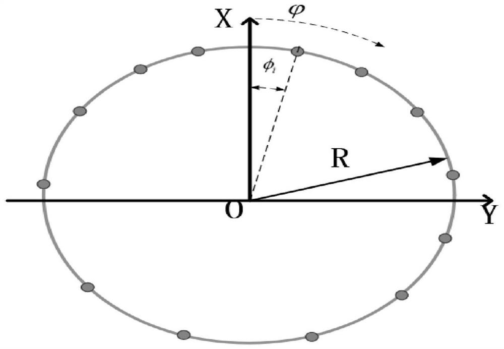
[0049] Consider a circular conformal array, which is composed of M=16 equally spaced array elements in different orientations, and the position angle of the array elements is set as Array element excitation Where R is the radius of the circular conformal array, |I i |follows the Hamming distribution, The direction diagram of the i-th array element is And when hour, In order to realize the array diagnosis function of the present invention method, now assume that the 3rd array element and the 10th array element damage in the array do not work at all and other array elements work normally, i.e. 1 3 =0,I 10 =0. Using the method of moments to obtain the phase modulus F of the array pattern p and the phase modulus coefficient f of the array element pattern p ,Right now Define the aspect ratio where p is the pattern number and is an integer and -P≤p≤P. therefore can be expressed as According to the literature Josefsson, L., Persson, P.: 'Conformal array antenna...

Embodiment 2

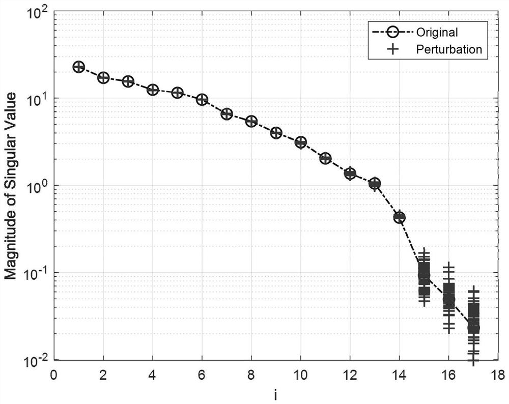
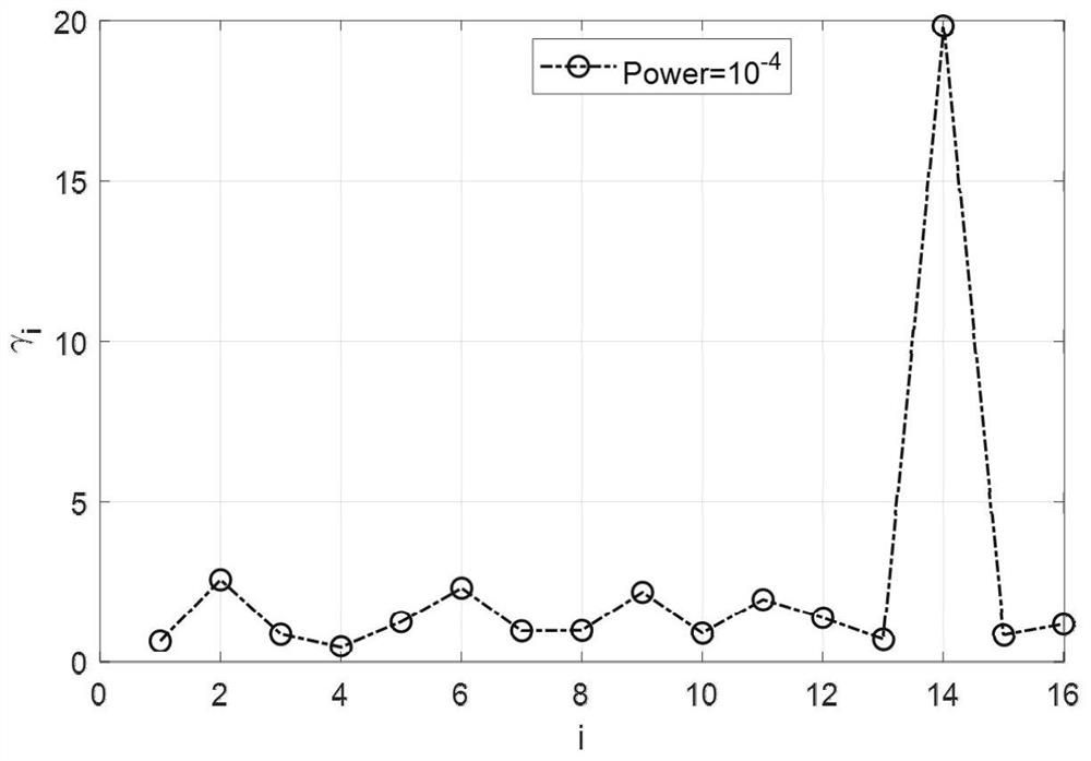
[0052] In order to further demonstrate the diagnostic performance of the method of the present invention, a non-uniform circular ring array is now considered, and the position angle φ of each array element i and Incentive I i A perturbation is performed, and the sixth array element and the ninth array element are not working at all, and the obtained circular array pattern and the array element pattern both contain inherent Gaussian white noise of the same power. The specific array parameter settings are shown in the Array configuration column in Table 1. In order to quantitatively describe the diagnostic performance of the method of the present invention, the array element position angle φ is defined i root mean square diagnostic error Root mean square diagnostic error of normalized array element excitation amplitude Array element excitation phase root mean square diagnostic error In the formula and The array element configuration parameters obtained by the method d...


PUM


Abstract

The invention discloses a circular ring array diagnosis method based on phase mode space parameter estimation, and relates to the field of array antenna diagnosis. Comprising the following steps: 1) obtaining an array far-field pattern of a to-be-diagnosed circular conformal array and a far-field pattern of array elements in the array through testing; 2) converting the obtained array directional diagram and the array element directional diagram in the array into an array directional diagram phase-mode coefficient and an array element directional diagram phase-mode coefficient respectively by using a moment method; 3) obtaining a phase-mode coefficient ratio in a harmonic form by using the array directional diagram phase-mode coefficient and the array element directional diagram phase-mode coefficient; 4) estimating a parameter of a phase-mode coefficient ratio by using a unitary matrix pencil algorithm; and 5) determining to-be-diagnosed array parameters by using the estimated parameters to complete array diagnosis. A circular ring conformal array diagnosis problem is converted into a parameter estimation problem of a phase-mode space undamped complex exponential signal, a complex circular ring conformal array diagnosis problem is solved in an analytic mode, and rapid and accurate diagnosis of the circular ring conformal array is realized.

Description

technical field [0001] The invention relates to the field of array antenna diagnosis, in particular to a method for diagnosing a ring array based on phase model space parameter estimation. Background technique [0002] Compared with a single antenna, array antennas arranged according to certain rules have the advantages of stronger directivity, flexible beamforming and scanning capabilities, which make array antennas widely used in wireless communication, electronic countermeasures, target recognition and other fields. With the development of wireless communication technology, the scale of array antennas has also become larger. However, the appearance of some damaged units in an array antenna composed of hundreds or thousands of elements is inevitable. The appearance of damaged array elements will inevitably lead to the deterioration of the performance of the entire array, such as the increase of the sidelobe level of the array pattern, the null shift, the decrease of the a...

Claims


Application Information

Patent Timeline
Patent Type & Authority Applications(China)
IPC IPC(8): G06F30/20G06F17/16G06F17/18G06F111/10
CPCG06F30/20G06F17/16G06F17/18G06F2111/10
Inventor 孔斌刘颜回陈礼阳孙嘉璐
Owner XIAMEN UNIV
Learn More