Steel bar component quality automatic detection method based on three-dimensional laser scanning

An automatic detection and three-dimensional laser technology, applied in the direction of measuring devices, optical devices, instruments, etc., can solve the problems of high labor intensity, inability to fully reflect the forming quality of steel parts, and low work efficiency, so as to achieve broad application prospects and improve the accuracy of measurement Effects on Accuracy and Productivity

Pending Publication Date: 2022-03-25
CCCC SECOND HARBOR ENG
View PDF0 Cites 0 Cited by
  • Summary
  • Abstract
  • Description
  • Claims
  • Application Information

AI Technical Summary

Problems solved by technology

The traditional method is to measure the acceptance items such as steel bar spacing, protective layer thickness, angle, etc. by sampling with a tape measure or a total station, which has the disadvantages of large measurement error and low work efficiency, especially for polygonal large-scale bridge towers with sections above 3m When the steel mesh is checked and accepted, the method of manual measurement is not only labor-intensive, but also low in work efficiency
In addition, traditional measurement methods can only select some points for measurement, which cannot fully reflect the forming quality of the entire steel bar part, and the accuracy of the measurement results cannot be guaranteed

Method used


Image

  • Steel bar component quality automatic detection method based on three-dimensional laser scanning
  • Steel bar component quality automatic detection method based on three-dimensional laser scanning
  • Steel bar component quality automatic detection method based on three-dimensional laser scanning

Examples


Embodiment Construction

[0040] The present invention will be further described in detail below in conjunction with the accompanying drawings, so that those skilled in the art can implement it with reference to the description.

[0041] It should be noted that the experimental methods described in the following embodiments, unless otherwise specified, are conventional methods, and the reagents and materials, if not otherwise specified, can be obtained from commercial sources; in the description of the present invention, The terms "landscape", "portrait", "top", "bottom", "front", "rear", "left", "right", "vertical", "horizontal", "top", "bottom", The orientation or positional relationship indicated by "inner", "outer", etc. is based on the orientation or positional relationship shown in the drawings, which is only for the convenience of describing the present invention and simplifying the description, and does not indicate or imply that the referred device or element must have Certain orientations, co...


PUM


Abstract

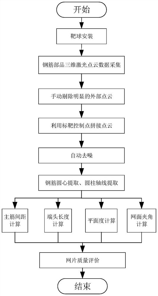
The invention discloses a method for automatically detecting the quality of a reinforcing steel bar component based on three-dimensional laser scanning. The method comprises the following steps: mounting a plurality of targets on the reinforcing steel bar component to be detected; scanning the construction area through a three-dimensional laser scanner to obtain original three-dimensional point cloud data; performing splicing and denoising processing on the original three-dimensional point cloud data in sequence to obtain three-dimensional point cloud data of the reinforcing steel bar component to be detected; respectively extracting circle center coordinates of different reinforcing steel bars and fitting to obtain axes of the corresponding reinforcing steel bars; calculating the critical dimension of the to-be-measured steel bar component; and evaluating the quality of the reinforcing steel bar component sections. According to the invention, batch splicing and denoising processing are carried out on the three-dimensional point cloud data acquired by the scanner, the key dimension data of the to-be-detected reinforcing steel bar component is rapidly and automatically calculated through a circle center and axis extraction method, and whether the quality of the reinforcing steel bar component is qualified or not is clearly and intuitively judged by combining a quality evaluation method. And the detection accuracy and the working efficiency are greatly improved.

Description

technical field [0001] The invention relates to the technical field of steel bar parts measurement. More specifically, the present invention relates to a method for automatically detecting the quality of steel bar parts based on three-dimensional laser scanning. Background technique [0002] At present, in the construction of bridge towers, the key dimensions need to be measured and accepted after the reinforcement parts are bound. The traditional method is to measure the acceptance items such as steel bar spacing, protective layer thickness, angle, etc. by sampling with a tape measure or a total station, which has the disadvantages of large measurement error and low work efficiency, especially for polygonal large-scale bridge towers with sections above 3m When the steel mesh is checked and accepted, the method of manual measurement is not only labor-intensive, but also low in work efficiency. In addition, traditional measurement methods can only select some points for mea...

Claims


Application Information

Patent Timeline
IPC IPC(8): G01B11/02G01B11/03G01B11/14G01B11/26G01B11/30
CPCG01B11/02G01B11/03G01B11/14G01B11/26G01B11/30Y02P90/30
Inventor 李冬冬朱明清程茂林吴中正陈斌张晓平夏昊涂同珩黄剑肖浩
Owner CCCC SECOND HARBOR ENG
Why Eureka
Try Eureka