
Novel rubber processing equipment

A processing equipment and rubber technology, applied in the field of new rubber processing equipment, can solve the problems of increased workload, low efficiency of grinding process, poor precision, etc., and achieve the effects of strong applicability, avoiding workload and cutting errors, and improving energy consumption

Pending Publication Date: 2022-03-25
吴年贵
View PDF1 Cites 1 Cited by
  • Summary
  • Abstract
  • Description
  • Claims
  • Application Information

AI Technical Summary

Problems solved by technology

[0006] refer to Figure 7 According to the document, it can be seen that when the cutting blade needs to be polished, the cutting blade needs to be returned to the original position. In the case of a large rubber strip output, in order to polish it, it needs to be adjusted to return to the original position. After that, it needs to be readjusted to the position before grinding, which increases the workload of adjustment and causes poor precision. In addition, during the grinding process, the cutting blades on both sides of the cutting blade cannot be polished at the same time, and only one side can be ground. On the other hand, the grinding process is also less efficient

Method used


Image

  • Novel rubber processing equipment
  • Novel rubber processing equipment
  • Novel rubber processing equipment

Examples


Embodiment 1

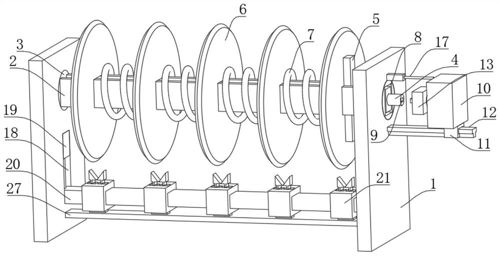
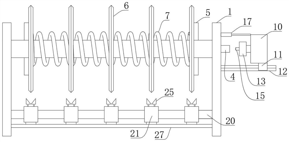
[0038] refer to Figure 1-8, a new type of rubber processing equipment, including two vertical boards 1, a long square frame 2 is arranged between the two vertical boards 1, indicating that the sides of the long square frame 2 are square, which is convenient for torque transmission, and the long square Both ends of the frame 2 are integrally formed with rotating disks 3, and the two rotating disks 3 are respectively connected in rotation with the vertical plate 1 located close to each other using bearings. The rotating disks 3 are set to facilitate rotation. Two-way threaded rod 4, the cross-sectional diameter of two-way threaded rod 4 is smaller than the distance between the inner walls on both sides of the elongated box 2, the two-way threaded rod 4 is in clearance fit with the elongated box 2, and the right end of the two-way threaded rod 4 runs through the elongated box 2 and is set , the vertical plate 1 on the right side is connected with the rotating disk 3 and the two-...

Embodiment 2

[0051] The difference between this embodiment and Embodiment 1 lies in that the elastic constants of the plurality of first springs 7 are different.

[0052] The above-mentioned embodiment 1 is suitable for cutting equal-width rubber strips, but in a special scenario, when it is necessary to cut rubber strips of different widths at one time, embodiment 1 cannot be applied.

[0053] In order to apply to special scenarios, the first spring 7 with different elastic coefficients can be selected according to the needs. The yield strength of each first spring 7 is different, and the degree of compression under the influence of external force is also different. Under this principle, the cutting blade can be adjusted without equal width. .

Embodiment 3

[0055] The difference between this embodiment and Embodiment 1 is that the elastic device includes a shielding plate 28 coaxially embedded on the two cutting blades 6, and the opposite sides of the two shielding plates 28 are sealed and fixedly connected with a shielding cover 29. The plate 28 and the shielding cover 29 can prevent the magnetic field of the electromagnetic device 30 from affecting other structures, the influence of the electromagnetic device 30 on the cutting blade 6, and the influence between the electromagnetic device 30 and the electromagnetic device 30. The opposite sides of each shielding plate 28 are symmetrically fixed. There are electromagnetic means 30, two electromagnetic means 30 are arranged opposite to each other.

[0056] In this embodiment, the electromagnetic device 30 is used to replace the first spring 7. The advantage is that the loss of the spring will not occur. In addition, the electromagnetic intensity can be set according to the specific...


PUM


Abstract

The invention discloses novel rubber processing equipment which comprises two vertical plates, a long square frame is arranged between the two vertical plates, rotating discs are integrally formed at the two ends of the long square frame, the two rotating discs are rotationally connected with the vertical plates close to the rotating discs through bearings correspondingly, and two-way threaded rods are rotationally connected to the inner walls of the two sides of the long square frame. The right end of the two-way threaded rod penetrates through the long square frame, the vertical plate and the rotating disc located on the right side and the two-way threaded rod are connected with a driving switching device, two pushing plates are symmetrically connected to the two-way threaded rod in a threaded mode, and the long square frame is slidably sleeved with a plurality of cutting blades at equal intervals. The cutting blades located on the two sides abut against and make contact with the two pushing plates correspondingly, and an elastic device is connected between every two adjacent cutting blades. The cutting width can be equidistantly adjusted or unequidistantly adjusted according to requirements, meanwhile, the grinding efficiency is high, and the structure is more compact.

Description

technical field [0001] The invention relates to the technical field of rubber processing equipment, in particular to a novel rubber processing equipment. Background technique [0002] In the process of rubber production and processing, it needs to be cut into rubber strips of different widths according to requirements, so a rubber strip cutting machine is used, which can quickly complete rubber cutting, and the cutting efficiency is higher than that of manual labor. There is an authorized invention patent in China, and the patent publication number is that CN111185960B discloses a special equipment for rubber processing. [0003] This prior patent records in its embodiment 1: the adjustable size cutting mechanism 1e uses multiple cutting blades 1e4 to simultaneously cut the rubber cloth into strips, cuts the rubber cloth into multiple strips at one time, and passes through the first rotating cap 1e11 The distance between the cutting blade 1e4 and the cutting blade 1e4 is co...

Claims


Application Information

Patent Timeline
Patent Type & Authority Applications(China)
IPC IPC(8): B26D1/15B26D7/12B26D7/26
CPCB26D1/15B26D7/12B26D7/2635
Inventor 吴年贵
Owner 吴年贵
Learn More