
A stamping packaging automation integrated equipment

A technology of integrated equipment and punching dies, which is applied in the field of stamping and packaging automation integrated equipment, can solve the problems of low production efficiency, high cost, and large space occupied by equipment, so as to save space occupied by equipment, ingenious mold structure design, labor cost and occupation. The effect of ground space

Active Publication Date: 2018-07-17
CHENGDU HOMIN TECH
View PDF4 Cites 0 Cited by
  • Summary
  • Abstract
  • Description
  • Claims
  • Application Information

AI Technical Summary

Problems solved by technology

Therefore, from production to packaging of SMD electronic components, at least two pieces of equipment are needed, one is stamping equipment, and the other is packaging equipment, so that the two pieces of equipment need at least two workers to operate, and there are transshipment costs in between, generally speaking , the production of SMD electronic components needs to go through two steps of stamping and packaging, the cost is high, and the production efficiency is low, and multiple devices occupy a large space

Method used


Image

  • A stamping packaging automation integrated equipment
  • A stamping packaging automation integrated equipment
  • A stamping packaging automation integrated equipment

Examples


Embodiment Construction

[0025] The present invention will be further described below in conjunction with the accompanying drawings, but the protection scope of the present invention is not limited to the following description.

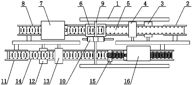
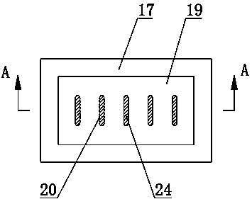
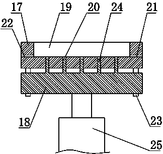
[0026] Such as figure 1 As shown, a stamping and packaging automation integrated equipment, including a bracket 1, a material tape feeding mechanism, a material tape dragging mechanism 7, a reverse die 6, a suction mechanism 10, a carrier tape feeding mechanism, a film coating mechanism 15 and a carrier tape dragging mechanism Mechanism 16, the support 1 is provided with a strip groove along its length direction, the strip feeding mechanism is arranged at the entrance of the strip groove, the strip 5 is assembled in the strip groove, and the reverse die 6 is arranged at the strip groove In the middle part of the back punching die 6, the product is stamped out from the bottom to the top of the material belt 5, and a material belt dragging device capable of intermittently dragg...


PUM


Abstract

The invention relates to automated stamping and packaging integrated equipment. The automated stamping and packaging integrated equipment comprises a support, a material belt feeding mechanism, a material belt dragging mechanism, an inverted stamping die, a material suction mechanism, a carrying belt feeding mechanism, a film covering mechanism and a carrying belt dragging mechanism. A material belt groove is formed in the support in the length direction of the support. The material belt feeding mechanism is arranged at an inlet of the material belt groove. The inverted stamping die is arranged in the middle of the material belt groove. Products are obtained through stamping of the inverted stamping die toward a material belt from bottom to top. The material belt dragging mechanism is arranged above the position, at the side of the inverted stamping die, of the material belt groove. A transverse-movement guide rail is transversely mounted at the position, above the inverted stamping die, of the support. The material suction mechanism is mounted on the transverse-movement guide rail in a matched manner. The support is further provided with a carrying belt groove. The carrying belt feeding mechanism is arranged at an inlet of the carrying belt groove. The film covering mechanism is mounted on the support and located at the side, close to an outlet of the carrying belt groove, of the transverse-movement guide rail. The carrying belt groove is further provided with the carrying belt dragging mechanism. The automated stamping and packaging integrated equipment has the beneficial effects that stamping and packaging are integrated, and labor cost and occupied space are saved.

Description

technical field [0001] The invention relates to the technical field of stamping and packaging of electronic components, in particular to an automated integrated equipment for stamping and packaging. Background technique [0002] SMD electronic components are usually stamped and formed, and then collected in the feeding mechanism, and then used as a carrier tape for packaging and transportation to meet the high-speed development needs of the SMT production line. Therefore, from production to packaging of SMD electronic components, at least two pieces of equipment are needed, one is stamping equipment, and the other is packaging equipment, so that the two pieces of equipment need at least two workers to operate, and there are transshipment costs in between, generally speaking , The production of SMD electronic components needs to go through two steps of stamping and packaging, the cost is high, and the production efficiency is low, and multiple devices occupy a large space. ...

Claims


Application Information

Patent Timeline
Patent Type & Authority Patents(China)
IPC IPC(8): B21D28/02B21D28/14B21D43/09B21D45/08B65B15/04
CPCB21D28/02B21D28/14B21D43/09B21D45/08B65B15/04
Inventor 刘呈明罗建国郭俊杰吴勇兵陈锦川朱浔田国富
Owner CHENGDU HOMIN TECH
Learn More