Thermal cutting device and method for steel plate

A thermal cutting and steel plate technology, applied in the direction of welding/welding/cutting items, laser welding equipment, manufacturing tools, etc., can solve the problem of power and thermal damage of the collection unit, and achieve the effect of air convection cooling treatment

Inactive Publication Date: 2022-03-25
安徽美合智能设备有限公司
View PDF0 Cites 0 Cited by
  • Summary
  • Abstract
  • Description
  • Claims
  • Application Information

AI Technical Summary

Problems solved by technology

[0004] The purpose of the present invention is to provide a thermal cutting device and method for steel plates to solve the problem that medium-temperature cutting materials in the prior art tend to directly adhere to low-temperature collection units, and the high temperature of laser cutting will also cause damage to the power of the collection unit. Technical issues with heat damage

Method used


Image

  • Thermal cutting device and method for steel plate
  • Thermal cutting device and method for steel plate
  • Thermal cutting device and method for steel plate

Examples


Embodiment Construction

[0036]The technical solutions in the embodiments of the present invention will be clearly and completely described below in conjunction with the accompanying drawings in the embodiments of the present invention. Obviously, the described embodiments are only some of the embodiments of the present invention, not all of them. Based on the embodiments of the present invention, all other embodiments obtained by persons of ordinary skill in the art without creative work all belong to the protection scope of the present invention.

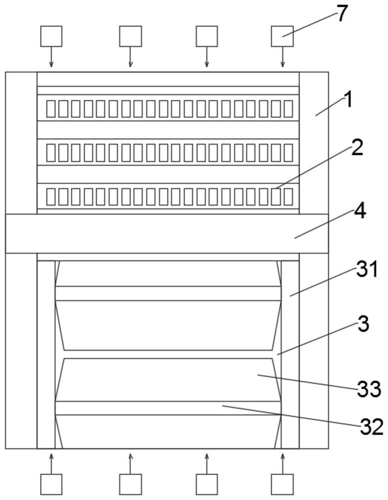
[0037] Such as figure 1 As shown, the present invention provides a thermal cutting device for steel plates. In this embodiment, an inclined baffle is set between the bed on which the steel plate is placed and the collection unit for cutting material. The inclined baffle can guide the cutting material and collect the cutting material. The heat insulation treatment of the unit, at the same time, the lower end of the inclined baffle forms an airflow for air ...


PUM


Abstract

The thermal cutting device comprises a driving seat and a supporting bed body driven by the driving seat, a cutting material storage mechanism is arranged below the supporting bed body, and a laser cutting mechanism moving along the supporting bed body is arranged between two side plates of the supporting bed body. The laser cutting mechanism enables cutting materials obtained after the steel plate is cut to fall into the cutting material storage mechanism to be collected. The cutting material storage mechanism comprises a loading frame arranged below the driving seat and partition beam plates arranged in the loading frame, two inclined baffles are installed on the lower end face of each partition beam plate, and a triangular cavity is formed between the two inclined baffles installed on each partition beam plate; a preheating and air cooling mechanism integrating electric heating and air cooling functions is arranged in the triangular cavity; the preheating and air cooling mechanism preheats the inclined baffle and performs air cooling on the cutting material; according to the laser cutting device, heat insulation treatment of laser cutting and cooling and adhesion prevention of a cutting material are achieved.

Description

technical field [0001] The invention relates to the technical field of steel plate cutting, in particular to a thermal cutting device and method for steel plates. Background technique [0002] Thermal cutting refers to the method of using concentrated heat energy to melt or burn and separate materials. According to the type of heat energy used, thermal cutting is divided into: ① gas cutting (flame cutting), which uses the flame produced by the mixed combustion of combustible gas and oxygen to melt the metal and cut it. The cut is formed by blowing off. The combustible gas is generally acetylene gas, but also petroleum gas, natural gas or coal gas. ②Plasma arc cutting, using the plasma arc as the heat source, melting the metal with the help of high-speed thermal ion gas (such as nitrogen, argon, argon-nitrogen, argon-hydrogen mixed gas) and blowing it off to form a slit, there are small current plasma arc cutting, There are 3 types of high current plasma arc cutting and wate...

Claims


Application Information

Patent Timeline
Patent Type & Authority Applications(China)
IPC IPC(8): B23K26/14B23K26/38B23K26/70
CPCB23K26/38B23K26/14B23K26/702B23K2101/18B23K2103/04
Inventor 王小平齐海兵
Owner 安徽美合智能设备有限公司
Why Eureka
Try Eureka