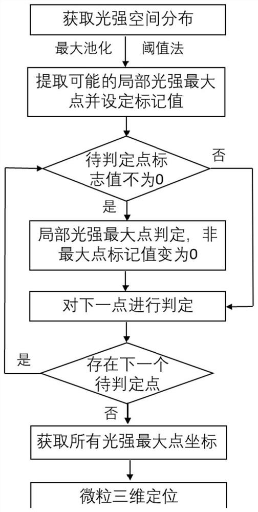
Three-dimensional rapid positioning method for particles
A three-dimensional positioning and particle technology, which is applied in image analysis, image enhancement, instruments, etc., can solve the problems of particle number influence, large data volume, and long time consumption, and achieve the effect of reducing hardware cost, compressing memory usage, and improving computing speed
- Summary
- Abstract
- Description
- Claims
- Application Information
AI Technical Summary
Problems solved by technology
Method used
Image

Examples
Embodiment 1
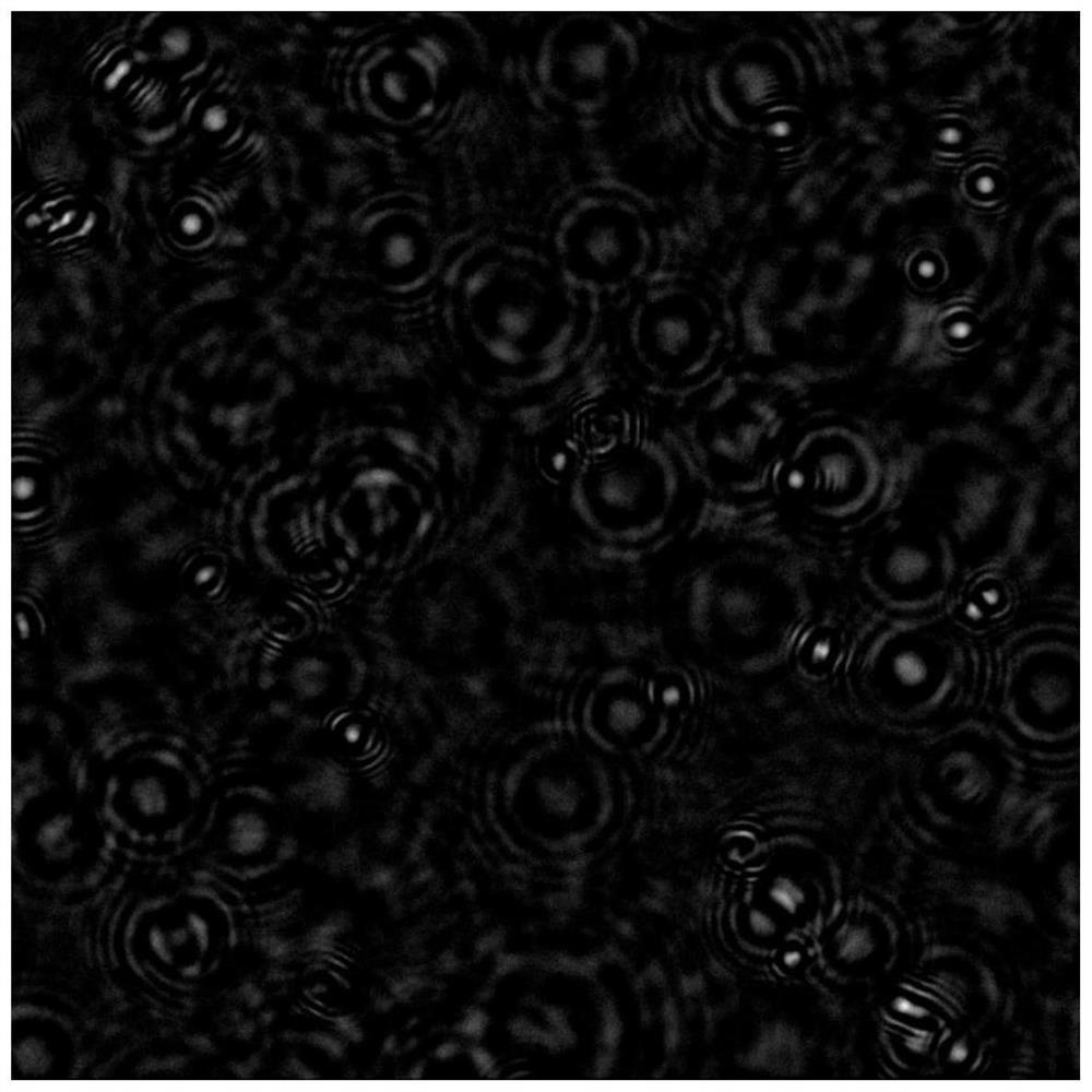
[0035] The embodiment of the present invention provides an experimental result of using a coaxial holographic imaging system for three-dimensional positioning of Escherichia coli. The light source used in the experiment is an LED light source with a wavelength λ=505nm, and the magnification of the holographic imaging system is 40x. Using a black-and-white camera with a pixel number of 1024*1024 and a pixel side length of 6.5 μm, the out-of-focus holographic imaging of the Escherichia coli liquid sample was obtained figure 2 ,in figure 2 Background subtraction has been performed.
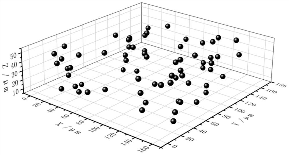
[0036] Considering the calculation speed and accuracy, the embodiment of the present invention tracks the bacteria particles within the range of 3.5 μm to 63.5 μm from the imaging surface. According to the pixel side length and magnification, the distance between adjacent reconstructed light intensity images should be 0.1625 μm. Combined with the reconstruction distance, the distance between the r...
Embodiment 2
[0041] The embodiment of the present invention provides an experimental result of three-dimensional positioning of PS plastic balls with a diameter of 0.8 μm dispersed on the same plane using a coaxial holographic imaging system. The light source used in the experiment is an LED light source with a wavelength of λ=450nm. The system magnification is 40x. Using a black-and-white camera with a pixel number of 1024*1024 and a pixel side length of 6.5 μm, the defocused holographic imaging of the plastic bead sample was obtained Figure 4 ,in Figure 4 Background subtraction has been performed.
[0042] In the embodiment of the present invention, tracking is performed within a range of 3.5 μm to 63.5 μm from the imaging plane. According to the pixel side length and magnification, the distance between adjacent reconstructed light intensity images should be 0.1625 μm. Combined with the reconstruction distance, the distance between the reconstructed light intensity surface and the im...
Embodiment 3
[0047] The embodiment of the present invention provides an experimental result of using a coaxial holographic imaging system to perform three-dimensional positioning on a Pseudomonas aeruginosa PAO1 bacterial liquid sample. The light source used in the experiment is an LED light source with a wavelength λ=505nm, and the magnification of the holographic imaging system is 40x . Using a black-and-white camera with a pixel number of 1024*1024 and a pixel side length of 6.5 μm, the defocused holographic imaging of the bacterial liquid sample was obtained Image 6 ,in Image 6 Background subtraction has been performed.
[0048] In the embodiment of the present invention, tracking is performed within a range of 3.5 μm to 63.5 μm from the imaging plane. According to the pixel side length and magnification, the distance between adjacent reconstructed light intensity images should be 0.1625 μm. Combined with the reconstruction distance, the distance between the reconstructed light int...
PUM
 Abstract
Description
Claims
Application Information
 - R&D
- Intellectual Property
- Life Sciences
- Materials
- Tech Scout
- Unparalleled Data Quality
- Higher Quality Content
- 60% Fewer Hallucinations
Browse by: Latest US Patents, China's latest patents, Technical Efficacy Thesaurus, Application Domain, Technology Topic, Popular Technical Reports.
© 2025 PatSnap. All rights reserved.Legal|Privacy policy|Modern Slavery Act Transparency Statement|Sitemap|About US| Contact US: help@patsnap.com