Heading machine based on visual positioning technology

A positioning technology and technology for roadheaders, which are applied in the field of roadheaders based on visual positioning technology, can solve problems such as inability to apply small-scale coal roadheading operations, inconvenient adjustment of coal roadway driving directions, and inability to effectively remote real-time monitoring, etc. Stable and regular, the top is firm, and the effect of easy post-construction

Pending Publication Date: 2022-03-22
XUHAI COLLEGE CHINA UNIV OF MINING & TECH
View PDF0 Cites 0 Cited by
  • Summary
  • Abstract
  • Description
  • Claims
  • Application Information

AI Technical Summary

Problems solved by technology

[0004] Existing roadheaders are not suitable for small-scale coal roadway excavation operations. It is inconvenient to adjust the direction of coal roadway excavation and the surface of the roadway is poor. There is a danger of landslides, and effective remote real-time monitoring is not possible. Therefore, we propose a roadheader based on visual positioning technology. solve the above problems

Method used


Image

  • Heading machine based on visual positioning technology
  • Heading machine based on visual positioning technology
  • Heading machine based on visual positioning technology

Examples


Embodiment 1

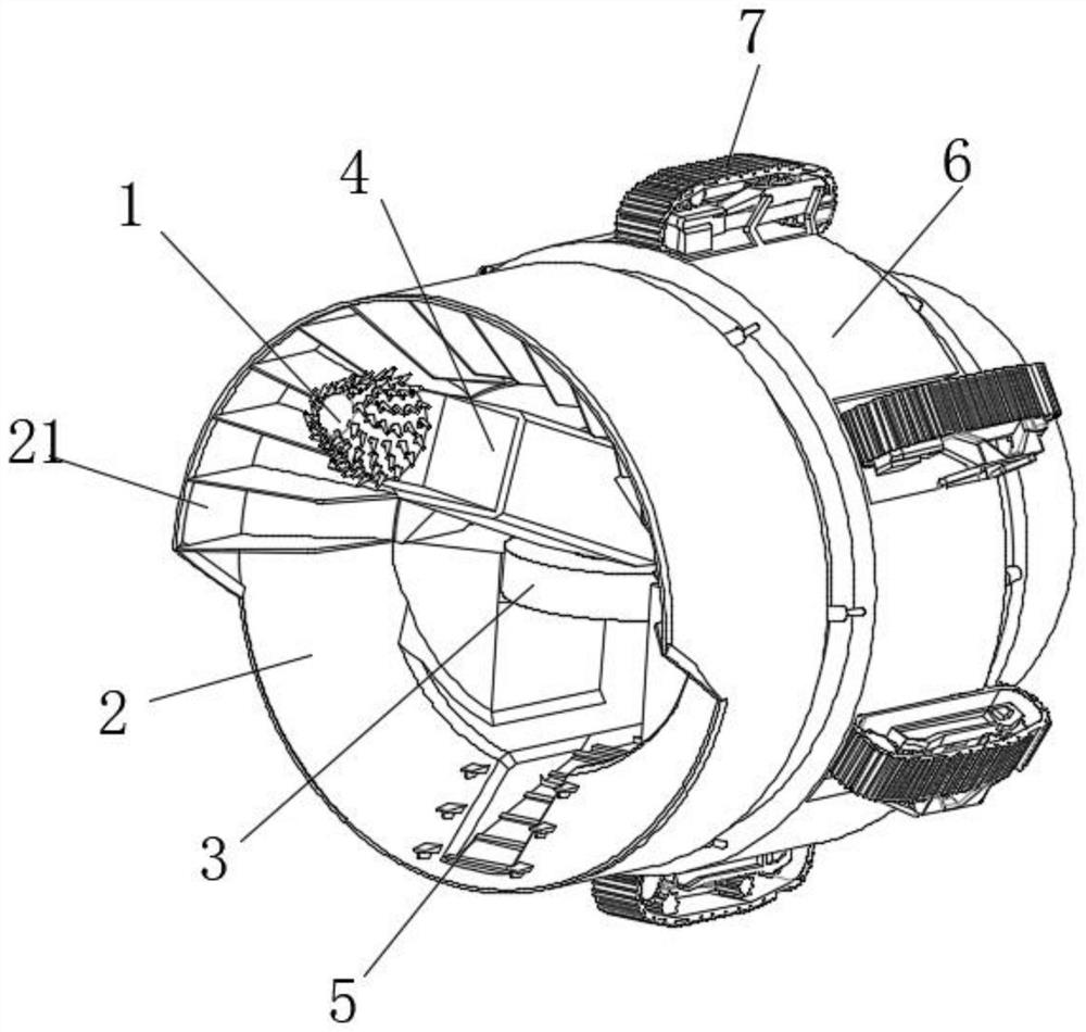
[0040] see Figure 1-10 , a roadheader based on visual positioning technology, including a cylindrical casing 2, a screw-in drill bit 1 and a control transfer base station, a rotating mechanism 3 is fixed inside the cylindrical casing 2, and an angle adjustment mechanism is fixed at the output end of the rotating mechanism 3 4. The screw-in drill bit 1 is fixed at the output end of the angle adjustment mechanism 4, the inner bottom of the cylindrical casing 2 is provided with a material conveyor belt 5, and the outer wall of the cylindrical casing 2 is provided with a spherical seat 23, which is connected to the rotating There is an annular support 6, the inner wall of the annular support 6 is provided with a ball groove 61 matching the spherical seat 23, and a plurality of telescopic rods 8 are arranged between both sides of the annular support 6 and the outer wall of the cylindrical casing 2, and a plurality of telescopic rods 8 are arranged. The rods 8 are equiangularly arr...


PUM


Abstract

The invention discloses a tunnel boring machine based on a visual positioning technology, and belongs to the field of tunnel boring machines, the tunnel boring machine comprises a cylindrical shell, a screw-in drill bit and a control transfer base station, a rotating mechanism is fixed in the cylindrical shell, an angle adjusting mechanism is fixed at the output end of the rotating mechanism, the screw-in drill bit is fixed at the output end of the angle adjusting mechanism, and the control transfer base station is fixed at the output end of the angle adjusting mechanism. A material conveying belt is arranged at the inner bottom of the barrel-shaped machine shell, a spherical seat is arranged on the outer wall of the barrel-shaped machine shell, an annular support is rotationally connected to the spherical seat, a ball groove matched with the spherical seat is formed in the inner wall of the annular support, a plurality of telescopic rods are arranged between the two sides of the annular support and the outer wall of the barrel-shaped machine shell, and the telescopic rods are evenly distributed at equal angles. A remote control mode is adopted, and the tunneling machine is suitable for tunneling work of a small tunnel, high in tunneling efficiency, accurate in tunneling line, visual in whole-process control, high in safety coefficient, good in market prospect and suitable for popularization.

Description

technical field [0001] The invention relates to the field of roadheading machines, in particular to a roadheading machine based on visual positioning technology. Background technique [0002] The cantilever roadheader has been widely used because of its safety and reliability, and its single-feed efficiency is much higher than the traditional blasting technology. However, when the cantilever roadheader cuts coal and rock, due to the position of the driver, the driver can only see the cutting on one side, and the other side often needs a co-driver to watch and use lights to instruct the driver to cut. At the same time, Due to cutting dust and spraying water, it is difficult for the driver and the co-driver to see the relationship between the position of the cutting head and the outline of the roadway. Most of the cutting is based on empirical judgment, resulting in poor roadway forming quality, and it is even more difficult for the driver to grasp . [0003] As the main ene...

Claims


Application Information

Patent Timeline
Patent Type & Authority Applications(China)
IPC IPC(8): E21D9/10E21D9/00E21F17/00E21F17/18G01D21/02
CPCE21D9/10E21D9/003E21F17/00E21F17/18G01D21/02
Inventor 梁斌魏超仝军令王水林杨新意
Owner XUHAI COLLEGE CHINA UNIV OF MINING & TECH
Why Eureka
Try Eureka