
Tool for welding steel junction box and welding method

A junction box and tooling technology, which is applied in the direction of manufacturing tools, welding equipment, welding equipment, etc., can solve the problem of inability to realize batch welding operations of junction box and grounding jumper wiring, delay in the processing and production period of junction box, and inaccurate positioning of junction box and other problems, to achieve the effect of good promotion and use value, simple structure and easy processing

Active Publication Date: 2022-03-22
CHINA CONSTR EIGHTH ENG DIV
View PDF9 Cites 0 Cited by
  • Summary
  • Abstract
  • Description
  • Claims
  • Application Information

AI Technical Summary

Problems solved by technology

[0003] The technical task of the present invention is to provide a steel junction box welding tool and welding method to solve the inaccurate positioning of the junction box and the inability to realize the batch welding operation of the junction box and the ground jumper connection, which in turn causes the junction box processing and production period. Serious lag, cost increase problem

Method used


Image

  • Tool for welding steel junction box and welding method

Examples


Embodiment 1

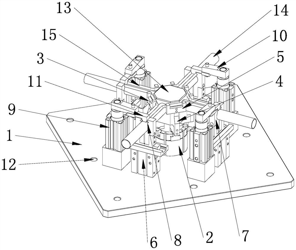
[0033] as attached figure 1 As shown, the steel junction box welding tooling of the present invention has a structure including a reference plate 1, which is square, and a number of evenly distributed installation holes 12 are opened on the outer edge of the square reference plate 1. The central position of the reference plate 1 is equipped with a clamping mechanism for the middle part of the grounding jumper wire, and four junction box wire tube clamping mechanisms are installed outside the middle part of the ground jumper wire clamping mechanism, and the four junction box wire tube clamping mechanisms are square and uniform Distributed on the reference plate 1, a grounding jumper end clamping mechanism is installed between two adjacent junction box wire tube clamping mechanisms, and the grounding jumper end clamping mechanism is spaced from the junction box wire tube clamping mechanism and grounded The clamping mechanism at the end of the jumper wire is located at the corner...

Embodiment 2

[0038] Steel junction box welding method of the present invention, this method is specifically as follows:

[0039] S1, open the jaw one 3 of the air claw cylinder one 2, open the jaw two 7 of the air claw cylinder two 6, and open the clamping cylinder 9 to the highest point;

[0040] S2. Put the junction box 13 above the jaw one 3;

[0041] S3, put the grounding jumper wire 15 on the wire tube 14 of the junction box;

[0042] S4, start the air claw cylinder one 2, and clamp the middle part of the junction box 13 and the ground jumper 15 through the clamp claw one 3;

[0043] S5, start the air claw cylinder 2 6, clamp the end of the junction box line pipe 14 by the jaw 2 7, and simultaneously position the grounding jumper wire 15;

[0044] S6, start the clamping cylinder 9, and clamp the end of the ground jumper 15 through the pressing plate 11;

[0045] S7, welding junction box 13 and ground jumper wire 15;

[0046] S8. After the welding operation is completed, open the c...


PUM


Abstract

The invention discloses a tool for welding a steel junction box and a welding method, belongs to the technical field of junction box welding, and aims to solve the technical problems that the junction box is inaccurate in positioning and cannot realize batch welding operation of the junction box and grounding overline wiring, so that the processing and manufacturing period of the junction box is severely lagged, the cost is increased and the working efficiency is high. According to the technical scheme, the grounding jumper wire clamping device comprises a reference plate, a grounding jumper wire middle portion pressing mechanism is arranged at the center of the reference plate, four junction box wire pipe clamping mechanisms are arranged on the outer side of the grounding jumper wire middle portion pressing mechanism, and the four junction box wire pipe clamping mechanisms are evenly distributed on the reference plate in a square shape; a grounding jumper terminal clamping mechanism is arranged between every two adjacent junction box wire pipe clamping mechanisms, and the grounding jumper terminal clamping mechanisms are located at the corners of the four junction box wire pipe clamping mechanisms distributed in a square shape.

Description

technical field [0001] The invention relates to the technical field of junction box welding, in particular to a tool for welding a steel junction box and a welding method. Background technique [0002] The steel junction box is one of the electrical accessories. The junction box is used as a transitional part at the wire joint (the corner of the wire pipe). The wire pipe is connected to the junction box to protect and connect the wires. At present, in the centralized processing operation on site, the production process is as follows: pipe cutting machine cutting pipe → steel pipe threading → steel pipe flaring → stamping machine making grounding jumper wires → manual assembly of steel junction boxes → welding robot batch welding grounding jumper wires → end . The main problem of this process is in the welding operation of the grounding jumper wire and the junction box. Due to the accuracy problem, the positioning of the steel junction box is often inaccurate, and the batch ...

Claims


Application Information

Patent Timeline
Patent Type & Authority Applications(China)
IPC IPC(8): B23K31/02B23K37/04
CPCB23K31/02B23K37/0435Y02E10/50
Inventor 殷飞杜娜李军刘庆喜孙士齐李志文殷利建
Owner CHINA CONSTR EIGHTH ENG DIV
Learn More