
Thermoelectric device

A thermoelectric device and electrode technology, which is applied to thermoelectric device components, thermoelectric devices that only use the Peltier or Seebeck effect, etc., can solve the problems of complex manufacturing process and increased thermal resistance, and achieve improved thermal flow performance, low thermal resistance, and excellent The effect of performance and high reliability

Pending Publication Date: 2022-03-18
LG INNOTEK CO LTD
View PDF0 Cites 0 Cited by
  • Summary
  • Abstract
  • Description
  • Claims
  • Application Information

AI Technical Summary

Problems solved by technology

In order to bond the heat dissipation member to the high temperature portion, thermal grease can be provided between the substrate of the high temperature portion and the heat dissipation member to bond the heat dissipation member to the high temperature portion, but due to the thermal grease, the thermal resistance may increase, and the manufacturing process may is complicated

Method used


Image

  • Thermoelectric device
  • Thermoelectric device
  • Thermoelectric device

Examples


Embodiment Construction

[0040] Hereinafter, exemplary embodiments of the present invention will be described in detail with reference to the accompanying drawings.

[0041] However, the technical spirit of the present invention is not limited to some exemplary embodiments disclosed below, but may be implemented in various forms. One or more components may be selectively combined and substituted for use among the exemplary embodiments without departing from the technical spirit of the present invention.

[0042] Also, unless otherwise defined, terms (including technical and scientific terms) used herein may be construed to have the same meaning as commonly understood by one of ordinary skill in the art to which this invention belongs. General terms such as those defined in dictionaries can be interpreted in consideration of the contextual meaning of the related art.

[0043] Also, the terminology used herein is intended to describe exemplary embodiments, and not to limit the invention.

[0044] In t...


PUM

PropertyMeasurementUnit
thicknessaaaaaaaaaa
thicknessaaaaaaaaaa
thicknessaaaaaaaaaa

Abstract

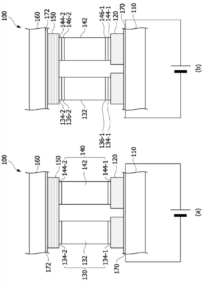
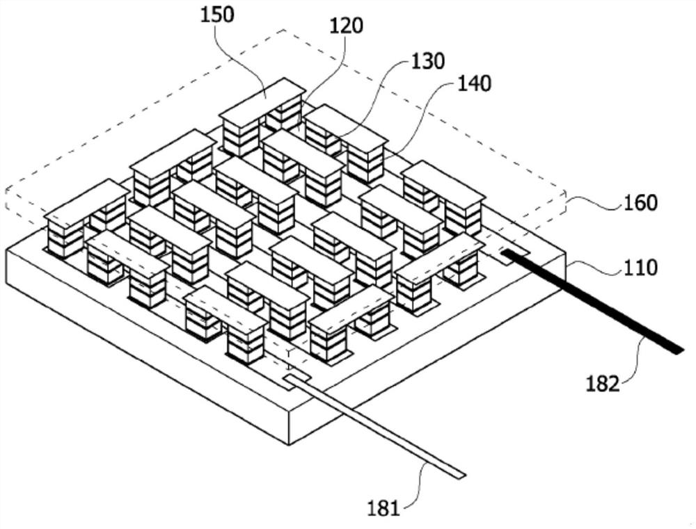
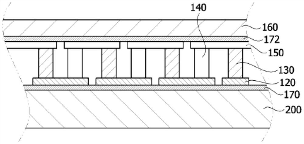
A thermoelectric device according to one exemplary embodiment of the present invention comprises: a heat dissipation member in which a groove is formed; the first electrode is arranged in the groove; a semiconductor structure disposed on the first electrode; a second electrode disposed on the semiconductor structure; a substrate disposed on the second electrode; and a sealing member disposed between the substrate and a sidewall of the recess.

Description

technical field [0001] The present invention relates to a thermoelectric device, and more particularly, to a structure of a thermoelectric device. Background technique [0002] The thermoelectric effect is a phenomenon that occurs due to the movement of electrons and holes in a material, and refers to the direct energy conversion between heat and electricity. [0003] A thermoelectric element generally refers to an element utilizing the thermoelectric effect, and the thermoelectric element has a structure in which a P-type thermoelectric material and an N-type thermoelectric material are combined between metal electrodes to form a PN junction pair. [0004] Thermoelectric elements can be classified as: elements that utilize resistance changes according to temperature changes; elements that utilize the Seebeck effect, which is a phenomenon in which an electromotive force is generated due to a temperature difference; elements that utilize the Peltier effect, which is a A phen...

Claims


Application Information

Patent Timeline
Patent Type & Authority Applications(China)
IPC IPC(8): H01L35/10H01L35/02H01L35/28
CPCH10N10/80H10N10/82H10N10/10H10N10/81H10N10/13H10N10/17
Inventor 朴正郁李丞镕陈昔玟
Owner LG INNOTEK CO LTD
Learn More