
Loudspeaker durability test monitoring device and test monitoring method

A technology of monitoring devices and horns, applied in the direction of electrical components, etc., can solve problems such as abnormal sounding frequency, abnormal wind speed, and inability to judge the sounding frequency and decibel value of the horn, so as to reduce artificial measurement errors, solve interference, and facilitate The effect of the operation

Pending Publication Date: 2022-03-18
SAIC-GM-WULING AUTOMOBILE CO LTD
View PDF0 Cites 0 Cited by
  • Summary
  • Abstract
  • Description
  • Claims
  • Application Information

AI Technical Summary

Problems solved by technology

[0003] The main defects of the horn durability test operation in the prior art are: after the cooling fan of the horn has been running for a long time, the life of the fan is almost exhausted, and its wind speed may be abnormal. The operator can’t test the wind speed through a handheld anemometer. To achieve 24h monitoring, the traditional fan cannot control the power of the speaker according to the actual wind speed, so it is necessary to monitor the wind speed of the fan and effectively cut off the power of the speaker; Nearly exhausted, the sounding frequency may be abnormal. The operator measures the decibel value of the horn sounding with a hand-held decibel meter. It is impossible to monitor the decibel value 24 hours a day, and it is also impossible to measure the sounding frequency.
The traditional horn power supply equipment cannot judge the sound frequency and decibel value of the horn, and it still supplies power to the horn when the sound frequency or decibel value of the horn is abnormal. This power supply device has limitations, so it is necessary to determine the sound frequency of the horn and decibel value for effective monitoring, so as to control the power supply of the speaker

Method used


Image

  • Loudspeaker durability test monitoring device and test monitoring method
  • Loudspeaker durability test monitoring device and test monitoring method

Examples


Embodiment Construction

[0024] Example embodiments will now be described more fully with reference to the accompanying drawings. Example embodiments may, however, be embodied in many forms and should not be construed as limited to the embodiments set forth herein; rather, these embodiments are provided so that this disclosure will be thorough and complete, and will fully convey the concept of example embodiments to those skilled in the art. The same reference numerals in the drawings denote the same or similar structures, and thus their detailed descriptions will be omitted.

[0025] The terms "a", "an", "the", "said" are used to indicate the presence of one or more elements / components / etc; the terms "comprising" and "have" are used to indicate an open-ended inclusion means and means that additional elements / components / etc. may be present in addition to the listed elements / components / etc.

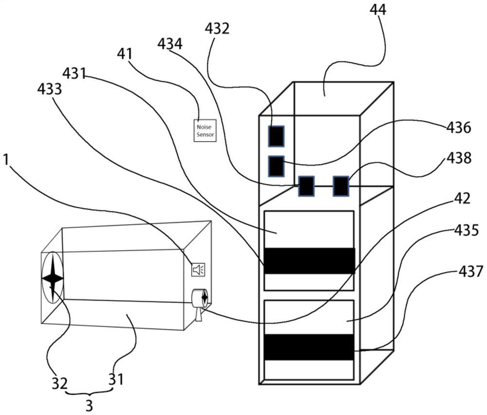
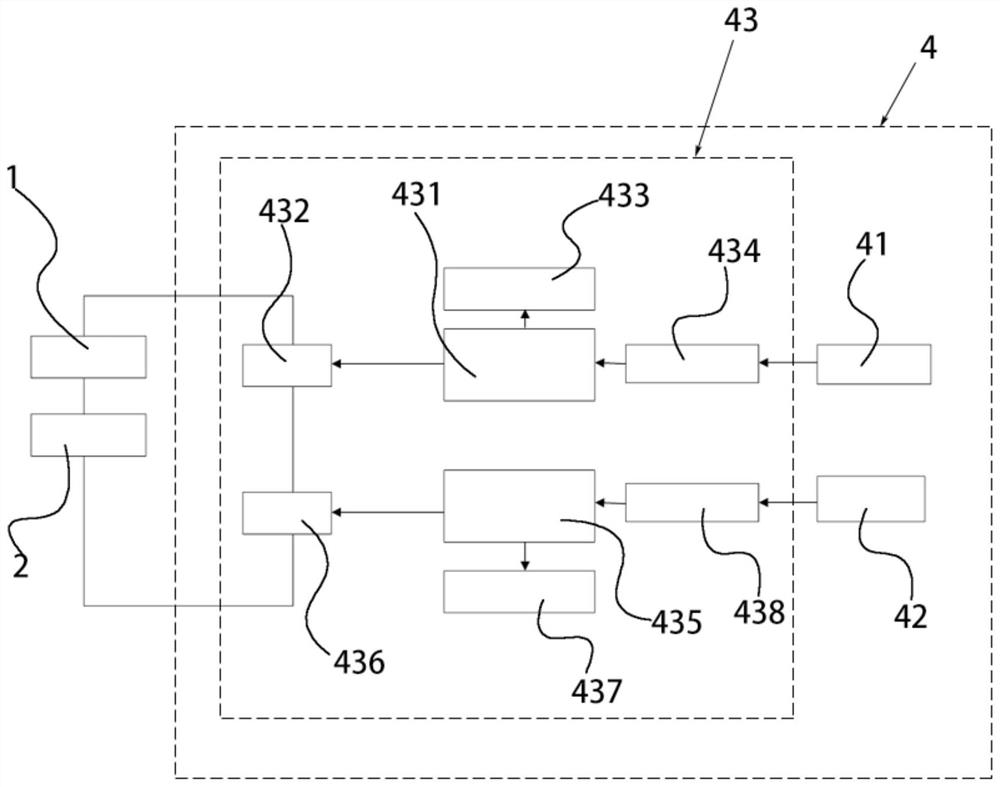
[0026] Such as figure 1 and figure 2 as shown, figure 1 A structural schematic diagram of a horn durabili...


PUM


Abstract

The invention provides a loudspeaker durability test monitoring device and a loudspeaker durability test monitoring method. The loudspeaker durability test monitoring device comprises a wind noise system and a monitoring assembly. The automobile horn is arranged in the wind noise system; the monitoring assembly comprises a sound sensing part, a wind speed sensing part and a monitoring controller, the sound sensing part is electrically connected with the monitoring controller, the wind speed sensing part is arranged in the wind noise system and electrically connected with the monitoring controller, the monitoring controller is electrically connected with the loudspeaker testing system, and the loudspeaker testing system is electrically connected with the monitoring controller. The loudspeaker testing system is switched off when the automobile loudspeaker is abnormal. According to the loudspeaker durability test monitoring device, the loudspeaker test system is timely disconnected through the sound relay to stop the test through the sound circuit board when the sound frequency of the automobile loudspeaker is abnormal, the working state of the loudspeaker can be monitored for 24 hours, the data acquisition precision is high, the operation is easy, and an alarm sound can be timely given to inform a tester in an abnormal condition.

Description

technical field [0001] The invention relates to the technical field of automobile electric horn testing, in particular to a horn durability test monitoring device and a horn durability test monitoring method. Background technique [0002] The durability test of the car horn is based on "GB15742-2019 Performance Requirements and Test Methods for Motor Vehicle Horns". The durability test of the horn is performed at a sound pressure level of not less than 105dB for 1s and a cycle of 50,000 cycles for 4s. It is not allowed in the test To adjust the horn, the horn should be cooled with an airflow of about 10m / s during the test. [0003] The main defects of the horn durability test operation in the prior art are: after the cooling fan of the horn has been running for a long time, the life of the fan is almost exhausted, and its wind speed may be abnormal. The operator can’t test the wind speed through a handheld anemometer. To achieve 24h monitoring, the traditional fan cannot co...

Claims


Application Information

Patent Timeline
Patent Type & Authority Applications(China)
IPC IPC(8): H04R29/00
CPCH04R29/001H04R2499/13
Inventor 唐华王磊毛艺覃力蓝政财
Owner SAIC-GM-WULING AUTOMOBILE CO LTD
Learn More