Aluminum-plated film composite paper flattening treatment equipment and treatment method
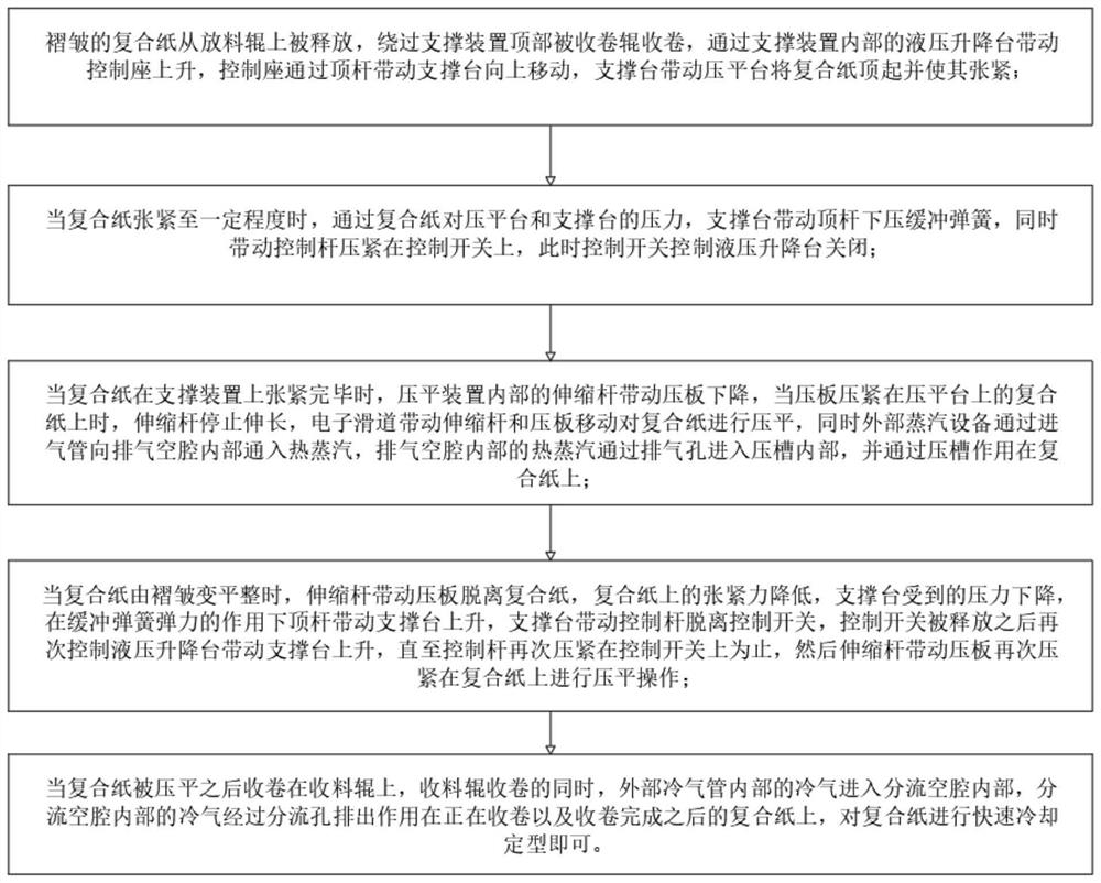
A technology for flattening and compounding paper, applied in thin material handling, machining/deformation, transportation and packaging, etc., it can solve the problems of lengthening, inability to adapt to compound paper, and inability to wrinkle and press, and achieves safe and reliable use. The leveling operation is thorough and the leveling effect is good.
- Summary
- Abstract
- Description
- Claims
- Application Information
AI Technical Summary
Problems solved by technology
Method used
Image
Examples
Embodiment 1
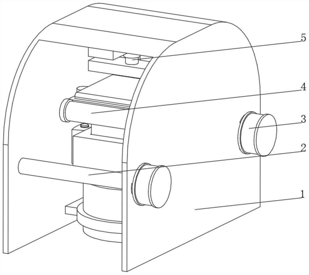
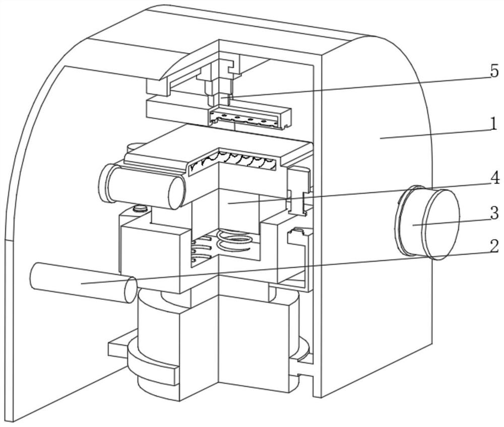
[0043] see Figure 2-4 , the present invention provides a technical solution: an aluminized film composite paper leveling treatment equipment, specifically comprising:
[0044] An outer frame 1, one end of the inner wall of the outer frame 1 is rotatably connected to a discharge roller 2, and one end of the inner wall of the outer frame 1 away from the discharge roller 2 is rotatably connected to a receiving roller 3,
[0045] Supporting device 4, the supporting device 4 is arranged in the part between the discharging roller 2 and the receiving roller 3 inside the outer frame 1;
[0046] A flattening device 5, the flattening device 5 is arranged on the top of the inner wall of the outer frame 1, and the bottom of the flattening device 5 faces the supporting device 4;
[0047] The feature of the aluminized film composite paper leveling treatment equipment is that the supporting device 4 includes:
[0048] Support platform 41, the two ends of the support platform 41 are fixedl...
Embodiment 2
[0055] see Figure 2-5 On the basis of Embodiment 1, the present invention provides a technical solution: the flattening device 5 includes an electronic slideway 51, the bottom of the electronic slideway 51 is slidably connected to a telescopic rod 52 through a slider, and the bottom of the telescopic rod 52 is fixedly connected to a pressing plate 53 , the bottom of the pressure plate 53 is provided with a pressure groove 54, the inside of the pressure plate 53 is provided with an exhaust cavity 55, the bottom of the exhaust cavity 55 is provided with an exhaust hole 56 communicating with the pressure groove 54, and the top of the electronic slideway 51 is connected to the inner wall of the outer frame 1 The top is fixedly connected, both ends of the pressure groove 54 are set in an open shape, and the side of the exhaust cavity 55 is connected with an air intake pipe 57, and the end of the air intake pipe 57 away from the exhaust cavity 55 communicates with external steam equ...
Embodiment 3
[0057] see Figure 2-6 , On the basis of Embodiment 1 and Embodiment 2, the present invention provides a technical solution: the receiving roller 3 includes a roller shaft 31, and the inside of the roller shaft 31 is provided with a cold air passage 32, and both ends of the cold air passage 32 are connected with a diverter plate 33 The side of the diverter plate 33 is fixedly connected with the roller shaft 31, the diverter plate 33 is provided with a diverter cavity 34, and the side of the diverter cavity 34 is provided with a diverter hole 35 communicating with the diverter cavity 34, and the diverter disc 33 is far away from the side of the roller shaft 31. One side is fixedly connected with a support shaft 36, one end of the support shaft 36 away from the diverter plate 33 is rotationally connected with the inner wall of the outer frame 1, one end of the support shaft 36 runs through the outer frame 1 and is fixedly connected with a drive motor, and the side of the diverter...
PUM
 Abstract
Description
Claims
Application Information
 - R&D
- Intellectual Property
- Life Sciences
- Materials
- Tech Scout
- Unparalleled Data Quality
- Higher Quality Content
- 60% Fewer Hallucinations
Browse by: Latest US Patents, China's latest patents, Technical Efficacy Thesaurus, Application Domain, Technology Topic, Popular Technical Reports.
© 2025 PatSnap. All rights reserved.Legal|Privacy policy|Modern Slavery Act Transparency Statement|Sitemap|About US| Contact US: help@patsnap.com


