Method for preparing nano material by electrodeposition based on corrosion of amorphous alloy anode material

A technology of amorphous alloys and anode materials, applied in nanotechnology, nanotechnology, nanotechnology, etc. for materials and surface science, can solve the problem of poor electrical conductivity of electrode materials, unfavorable nanostructures, uneven corrosion elements, etc. problems, to achieve the effect of avoiding poor electrode conductivity, stable reaction system, and easy control

Pending Publication Date: 2022-03-18
NANJING UNIV OF SCI & TECH
View PDF6 Cites 0 Cited by
  • Summary
  • Abstract
  • Description
  • Claims
  • Application Information

AI Technical Summary

Problems solved by technology

Most of the currently known methods of preparing nanostructures by means of electrodeposition are to deposit metal ions in the electrolyte to obtain nanostructure materials. This method has a problem of reaction stability during the preparation process; The mixture can be used as an electrode material only when it is compounded on a conductive substrate. The compounding process is cumbersome, and the compounded electrode material will have the problem of poor electrode conductivity.
In addition, in the process of using crystal corrosion deposition, due to the defects such as grain boundaries in the crystal, these defects will be corroded preferentially during corrosion, and the corrosion elements will be uneven, which is not conducive to the formation of nanostructures; on the other hand, the deposition process It is not easy to control, and a large number of columnar crystals will be generated, resulting in the inability to form nanoscale characteristic structures

Method used


Image

  • Method for preparing nano material by electrodeposition based on corrosion of amorphous alloy anode material
  • Method for preparing nano material by electrodeposition based on corrosion of amorphous alloy anode material
  • Method for preparing nano material by electrodeposition based on corrosion of amorphous alloy anode material

Examples


Embodiment 1

[0035] (1) According to the Zr:Al:Co atomic ratio of 56:16:28, a total of 40 g of Zr, Al, and Co pure metals (purity 99.99%) were taken, and ultrasonic cleaning was performed with acetone and deionized water respectively to remove surface pollutants. The cleaned Zr, Al and Co pure metals are mixed in the crucible in the electric arc melting furnace, and smelted under an argon atmosphere, and the smelting current is about 180A. During smelting, both sides of the alloy ingot are smelted twice, each time for about 3 minutes.

[0036] (2) Take Zr after smelting 56 Al 16 co 28 About 10g of the master alloy is placed at the bottom of a special quartz tube (diameter of the quartz tube is 16mm, and the bottom opening is 5mm). In an argon atmosphere, the ZrAlCo amorphous alloy strip is obtained by a single copper roll strip quenching method. The number of roll rotations is 2500 rpm, and the alloy is smelted to a molten state by induction heating for injection, and finally a Zr alloy...

Embodiment 2

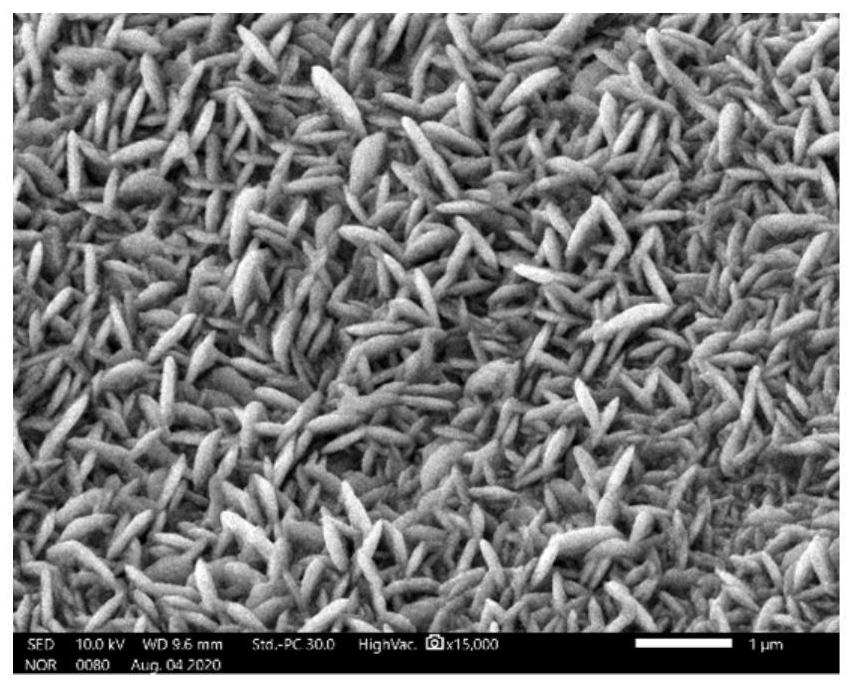
[0044] Step (1) and step (2) are the same as the first embodiment, the polarization potential in step (3) is adjusted to 2.5V vs. SCE, and other conditions remain unchanged.

[0045] When the potential is raised to 2.5V vs. SCE, the deposition potential of Zr and Co elements is reached at the same time, and finally a nanosheet structure containing Zr and Co elements is obtained, which is also consistent with Zr 56 Al 16 co 28 At 2.5V vs. SCE potential, the amorphous alloy can achieve the expected deposition of Zr and Co elements, and the composition deposition is controllable. It looks like image 3 The content of each element is shown in Table 2.

[0046] The EDS data of table 2 embodiment two

[0047] Elements Wt% At% O 11.68 34.66 co 73.25 58.14 Zr 15.07 7.72 Total 100.00 100.00

Embodiment 3

[0049] Step (1) and step (2) are the same as in Example 1. In step (3), the working electrode is adjusted to Co simple substance with the same area, and the polarization time is 1 h.

[0050] At this potential, the Co elemental working electrode corrodes very violently, and the reaction current is too large. Due to the excessively fast reaction rate, a large number of dendrites are formed on the foamed nickel substrate, and nanostructures cannot be obtained. The morphology is as follows Figure 4 The content of each element is shown in Table 3.

[0051] The EDS data of table 3 embodiment three

[0052] Elements Wt% At% O 8.54 25.59 co 91.46 74.41 Total 100.00 100.00


PUM


Abstract

The invention discloses a method for preparing a nano-structure material by electrodeposition based on corrosion of an amorphous alloy anode material, and the preparation method comprises the following steps: proportioning metal elementary substances according to a target alloy ZraAlbCocMd, and smelting to obtain a master alloy; wherein a is larger than or equal to 55 at.% and smaller than or equal to 56 at.%, b is larger than or equal to 13 at.% and smaller than or equal to 20 at.%, c is larger than or equal to 20 at.% and smaller than or equal to 28 at.%, d is larger than or equal to 0 at.% and smaller than or equal to 5 at.%, and M is any one of Nb, Cu, Ag and Ni metal elements; the obtained mother alloy is treated through a single-roller melt-spinning quenching method, so that a ZraAlbCocMd amorphous alloy strip is obtained; and in a standard three-electrode system, the obtained ZraAlbCocMd amorphous alloy strip is used as a working electrode, a target deposition substrate is used as a counter electrode, the ZraAlbCocMd amorphous alloy strip is corroded through a constant potential polarization method, and the required nano-structure material is deposited on the counter electrode. The method provided by the invention is more beneficial to reaction stability, the deposition process is easier to control, and a uniform nano-structure material can be directly deposited on the substrate.

Description

technical field [0001] The invention belongs to the technical field of nano-metal functional materials, and in particular relates to a method for preparing nano-structure materials by electrodeposition based on corroding amorphous alloy anode materials. Background technique [0002] The development of nanotechnology has made cobalt-based nanomaterials exhibit better electrochemical properties. Many studies in recent years have proved that cobalt-based nanomaterials have excellent electrochemical properties, and have been widely studied in the fields of supercapacitors, sensors, and electrocatalysis. And the lower cost of cobalt-based materials further increases its potential for large-scale production applications. [0003] Electrochemical deposition is one of the methods for constructing nanostructures. Compared with other methods, this method has the advantages of controllability, simple operation, high efficiency, no need for additional reagents and low equipment requirem...

Claims


Application Information

Patent Timeline
IPC IPC(8): B22D11/06C22C45/10C25D3/12C25D3/56C25D21/12C25F3/08B82Y30/00B82Y40/00
CPCB22D11/0611C22C45/10C25F3/08C25D3/12C25D3/562C25D21/12B82Y30/00B82Y40/00
Inventor 秦凤香李京豪淡振华陈峰池昱晨王杭宁
Owner NANJING UNIV OF SCI & TECH
Why Eureka
Try Eureka