
Pull rod type limiter

A limiter and pull-rod technology, applied in the field of pull-rod limiters, can solve the problem of no limiter, etc., and achieve the effects of good stress state, convenient disassembly and assembly, and reduction of initial collision force.

Pending Publication Date: 2022-03-15
NO 719 RES INST CHINA SHIPBUILDING IND
View PDF0 Cites 0 Cited by
  • Summary
  • Abstract
  • Description
  • Claims
  • Application Information

AI Technical Summary

Problems solved by technology

There is no limiter that fully meets this requirement in the prior art

Method used


Image

  • Pull rod type limiter
  • Pull rod type limiter

Examples


Embodiment 1

[0029] This embodiment provides a tie rod limiter with a high redundancy structure, a high security coefficient, and is widely applicable to impact protection of the device.

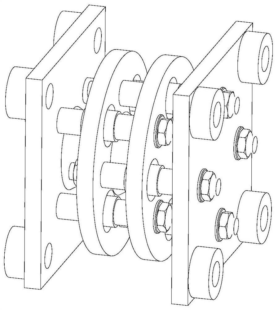
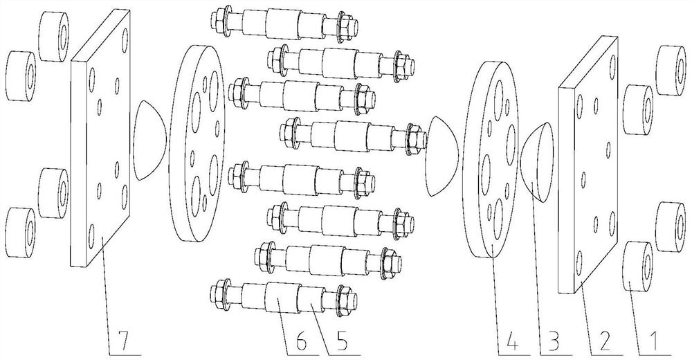
[0030] Such as figure 1 and figure 2 As shown, the tie rod limiter includes: cushion 1, upper bottom plate 2, buffer block 3, a limit disk 4, a limit shaft 5, buffer sleeve 6, and lower bottom plate 7;

[0031] The upper and lower bottom plate 7 is disposed in parallel, and the two limit trays 4 (here all the disc shaped structures) are disposed between the two, and the two or more limit shafts 5 (the number of limit shafts 5) Adjustable, so that the redundancy of the limiter can also be improved, and the force state of the limiter can also be improved, and the eight limit axes 5 are preferably passed through two limit trays 4, one or more The bit shaft 5 (preferably four limit axes 5) is fastened to the limit disk 4 (referred to as a lower limit disk) close to the lower bottom plate 7 by fasteners (such as ...

Embodiment 2

[0036] On the basis of Example 1, both the upper bottom plate 2 and the lower bottom plate 7 use a square structure to facilitate effectively utilizing the installation space of the upper bottom plate 2 and the lower bottom plate 7.

Embodiment 3

[0038] Based on the first embodiment, the upper bottom plate 2 and the lower bottom plate 7 are designed into a circular shape to accommodate more installation requirements.


PUM


Abstract

The invention discloses a pull rod type limiter which is characterized by comprising an upper bottom plate, a buffer block, a limiting disc, a limiting shaft, a buffer sleeve and a lower bottom plate, the upper bottom plate and the lower bottom plate are oppositely arranged in parallel, the two limiting discs are arranged between the upper bottom plate and the lower bottom plate in parallel, the two or more upper limiting shafts sequentially penetrate through the two limiting discs, one ends of the one or more upper limiting shafts are fixed to the lower limiting disc, and the other ends of the one or more upper limiting shafts are fixed to the upper bottom plate; one ends of the rest limiting shafts are fixed on the upper limiting disc, and the other ends are fixed on the lower bottom plate; the middle of each limiting shaft in the axial direction is coaxially sleeved with a buffering sleeve, the buffering sleeves, fixed between the lower limiting disc and the upper bottom plate, of the limiting shafts are in clearance fit with through holes formed in the upper limiting disc, and the buffering sleeves, fixed between the upper limiting disc and the lower bottom plate, of the limiting shafts are in clearance fit with through holes formed in the lower limiting disc. The end, facing the limiting discs, of the upper bottom plate, the end, facing the limiting discs, of the lower bottom plate and any opposite end faces of the two limiting discs are each provided with a buffer block.

Description

Technical field [0001] The present invention relates to the field of vibration noise control, and more particularly to a tie rod limiter. Background technique [0002] In order to improve the vibration isolation performance of the vibration isolation device, the deformation stability of the vibration isolating device is maintained, and the limiter is often applied to the vibration isolating device. The limiter is mainly to perform a limit effect under the impact condition, so the limiter needs huge impact. [0003] The limiter needs high security factor. There is no limiter that is fully compliant in the prior art. Inventive content [0004] In view of this, the present invention provides a tie rod limiter with a highly redundant structure, a high security coefficient, and can be widely applicable to impact protection of the device. [0005] The technical solution of the present invention is: a tie rod limiter comprising: upper bottom plate, buffer block, a limit disk, a limit a...

Claims


Application Information

Patent Timeline
Patent Type & Authority Applications(China)
IPC IPC(8): F16F15/04F16F15/08
CPCF16F15/04F16F15/08F16F2224/025F16F2226/04F16F2230/0023
Inventor 张针粒刘海建商超代成名戴睿婕郭寒贝谭海涛王强勇强磊
Owner NO 719 RES INST CHINA SHIPBUILDING IND
Learn More