
Strip-shaped steel shape corrector

A straightener and steel technology, which is applied in the field of strip steel shape straighteners, can solve problems such as inaccurate straightening, and achieve the effect of avoiding the increase of errors

Pending Publication Date: 2022-03-15
扬州润禾钢业科技有限公司
View PDF0 Cites 0 Cited by
  • Summary
  • Abstract
  • Description
  • Claims
  • Application Information

AI Technical Summary

Problems solved by technology

[0003] The purpose of the present invention is to address the shortcomings of the prior art, and use a single-chip computer and a laser rangefinder to calculate the deformation required to be squeezed when correcting the steel to match multiple groups of rollers composed of upper and lower rollers. Extruded from part to whole, designed a strip steel shape corrector, which solves the problem that there is no complete correction equipment for strip steel at present, so that the correction is inaccurate

Method used


Image

  • Strip-shaped steel shape corrector
  • Strip-shaped steel shape corrector
  • Strip-shaped steel shape corrector

Examples


Embodiment Construction

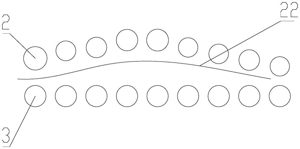
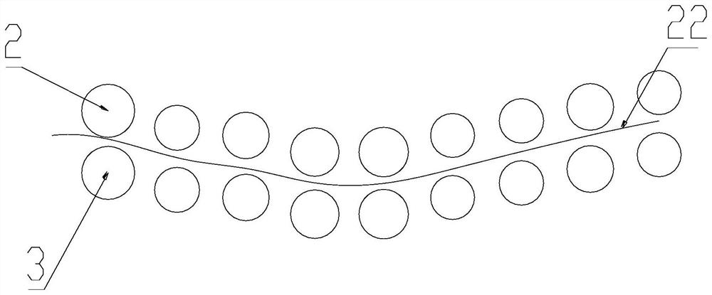
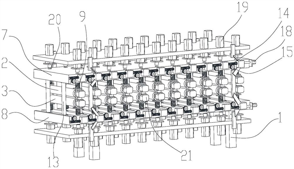
[0022] see Figure 1-5 , a strip-shaped steel shape corrector, comprising a frame 1, the frame 1 is provided with several upper rollers 2, several lower rollers 3, several extruding mechanisms, several laser rangefinders 4, and a single-chip microcomputer 5, the The upper roll 2 is located directly above the lower roll 3, the upper roll 2 and the lower roll 3 are parallel to each other, and the roll holders 10 of the upper roll 2 and the lower roll 3 are connected to the frame 1 through the slide bar 6 respectively. The top plate 7 and the bottom plate 8 are slidingly connected, the slide bar 6 is sleeved with a spring 9, the roller seat 10 of the upper roller 2 is provided with a laser rangefinder 4 on the side facing the top plate 7, and the lower roller 3 A laser range finder 4 is arranged on the side of the roller base 10 facing the bottom plate 8, and the side of the top plate 7 facing away from the roll base 10 and the side of the bottom plate 8 facing away from the roll...


PUM


Abstract

The invention belongs to the technical field of steel straightener manufacturing, and particularly relates to a strip-shaped steel shape straightener which comprises a rack, a plurality of upper rollers, a plurality of lower rollers, a plurality of extrusion mechanisms, a plurality of laser range finders and a single chip microcomputer are arranged on the rack, the upper rollers are located over the lower rollers, and the upper rollers are parallel to the lower rollers; roller seats of the upper roller and the lower roller are slidably connected with a top plate and a bottom plate of the rack through sliding rods correspondingly, the sliding rods are sleeved with springs, a laser range finder is arranged on the face, facing the top plate, of the roller seat of the upper roller, and a laser range finder is arranged on the face, facing the bottom plate, of the roller seat of the lower roller. The extrusion mechanisms are arranged at the positions, corresponding to the upper rollers and the lower rollers, of the face, back to the roller base, of the top plate and the face, back to the roller base, of the bottom plate correspondingly, the output end of the single-chip microcomputer is electrically connected with the extrusion mechanisms and the roller driving device, and the problem that at present, no equipment for completely correcting the strip-shaped steel exists, and correction is inaccurate is solved.

Description

technical field [0001] The invention belongs to the technical field of manufacturing steel straighteners, in particular to a strip-shaped steel shape straightener. Background technique [0002] After the strip steel is produced, the shape of the strip steel will change due to various external reasons, such as extrusion or collision, especially during the placement of the strip steel. Supports are set between the two ends of the bar-shaped steel, resulting in uneven stress on the bar-shaped steel. Under the action of gravity, the bar-shaped steel will bend, and after the bar-shaped steel bends, it is difficult to correct, especially the bar Steel also has certain toughness and elasticity, and the length of strip steel is relatively long, which makes the correction process very troublesome. The traditional correction method is that the worker places the bar steel on the bottom surface or the processing surface, and then applies force to the protruding side of the bar steel. ...

Claims


Application Information

Patent Timeline
IPC IPC(8): B21D3/05
CPCB21D3/05
Inventor 马俊杰
Owner 扬州润禾钢业科技有限公司
Learn More