
A compressor gas kinetic energy recovery device

A gas kinetic energy and recovery device technology, applied in the direction of machines/engines, mechanical equipment, etc., can solve problems such as kinetic energy waste, energy waste, unfavorable energy conservation and environmental protection, and achieve the effect of avoiding energy waste

Active Publication Date: 2019-12-27
江苏章鼓力魄锐动力科技有限公司
View PDF4 Cites 0 Cited by
  • Summary
  • Abstract
  • Description
  • Claims
  • Application Information

AI Technical Summary

Problems solved by technology

[0002] The compressor is mainly used to generate high-pressure gas, and the high-pressure gas needs to be stored in the gas storage tank. The compressor and the gas storage tank are connected by a gas transmission pipeline, and the gas transmission pipeline transports the high-pressure gas generated by the compressor to the gas storage tank, so There is always gas flow in the gas pipeline. The current compressor does not recycle the kinetic energy generated by the gas flow. A large amount of kinetic energy is wasted, resulting in serious energy waste, which is not conducive to energy conservation and environmental protection.

Method used


Image

  • A compressor gas kinetic energy recovery device
  • A compressor gas kinetic energy recovery device
  • A compressor gas kinetic energy recovery device

Examples


Embodiment Construction

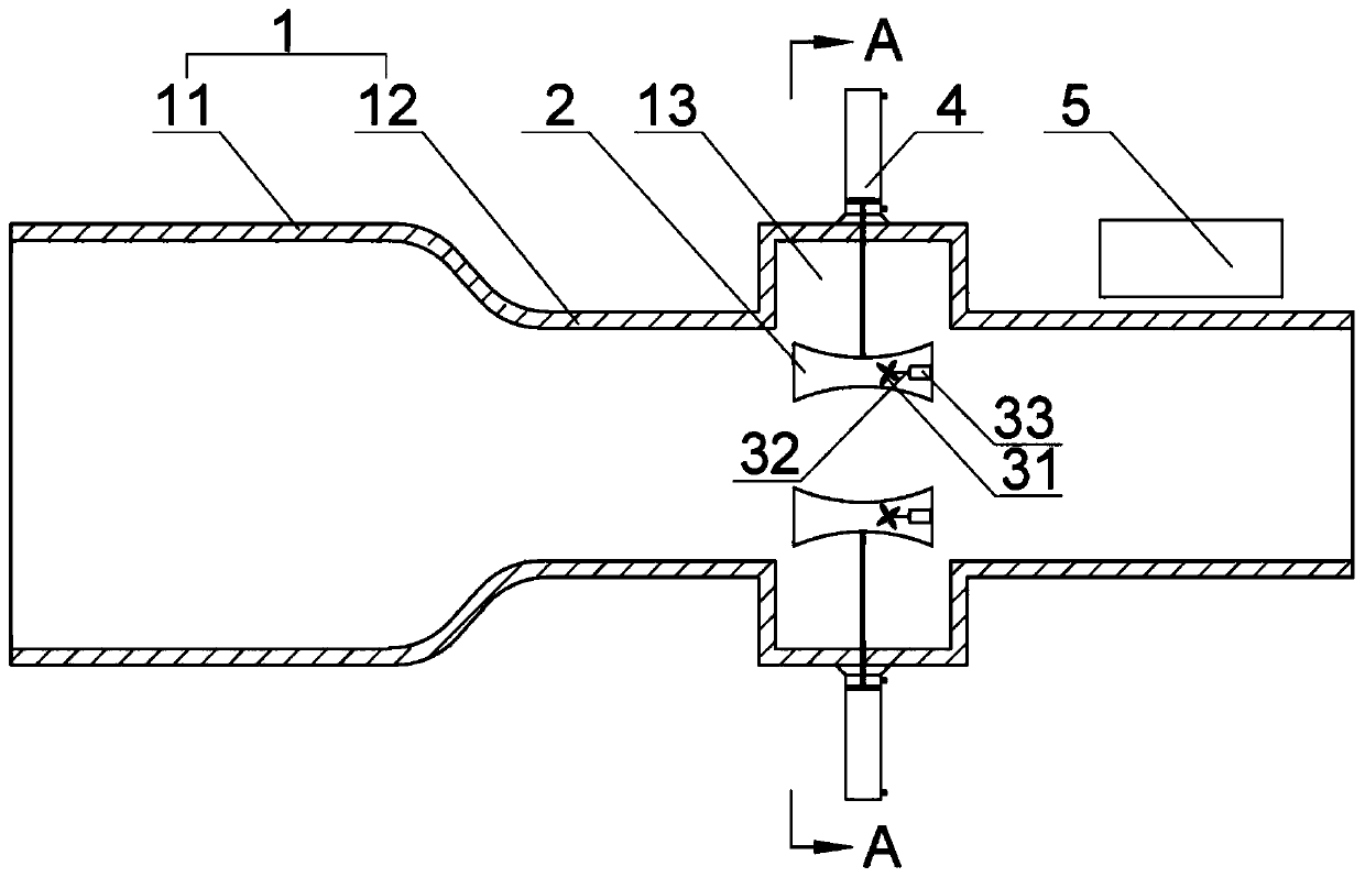
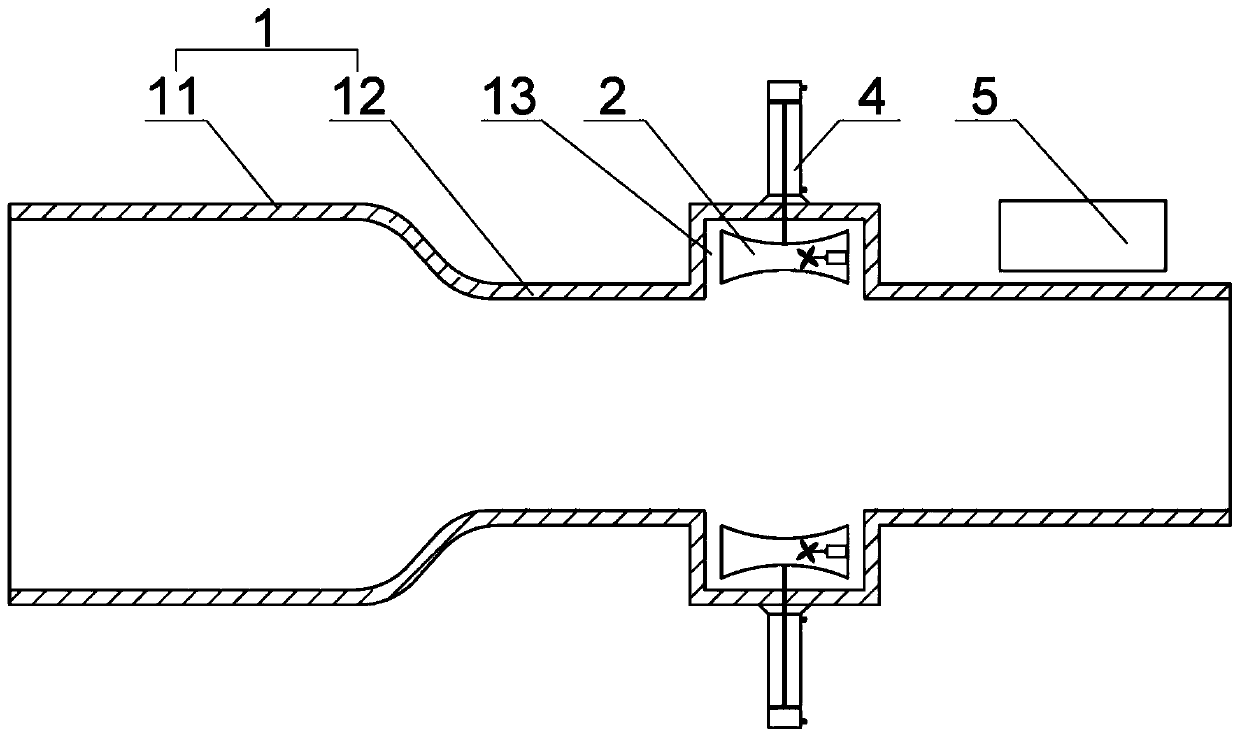
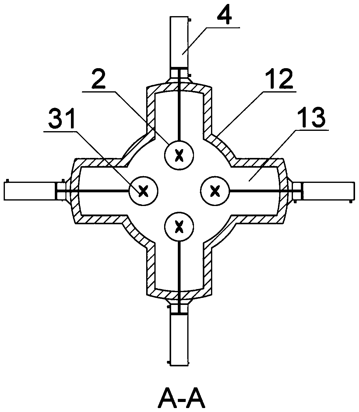
[0015] Such as Figure 1-3 as shown, figure 1 It is an axial sectional view of a compressor gas kinetic energy recovery device in working state proposed by the present invention, figure 2 It is an axial sectional view of a gas kinetic energy recovery device for a compressor proposed by the present invention when it is stopped working, image 3 It is a radial cross-sectional view of a compressor gas kinetic energy recovery device proposed by the present invention in working state.

[0016] refer to Figure 1-3 , a compressor gas kinetic energy recovery device proposed by the present invention comprises a main body 1, four Laval nozzles 2, four wind power generators and four hydraulic cylinders 4; the main body 1 communicates with the compressor exhaust pipe, The main pipe body 1 is provided with four receiving grooves 13 outward, the four receiving grooves 13 are located on the same radial surface of the main pipe body 1 and are evenly arranged along the circumference of th...


PUM


Abstract

The invention discloses a compressor gas kinetic energy recovery device. A main pipe body communicates with a compressor exhaust pipe; the main pipe body is outwards provided with a storage groove; aLaval nozzle is arranged in the main pipe body and can be stored in a storage groove; a piston rod of a hydraulic cylinder is connected with the Laval nozzle and is used for driving the Laval nozzle to move; a wind power generation mechanism is arranged in the Laval nozzle; when the wind power generation mechanism is in an operating state, the Laval nozzle is located outside the storage groove andwhen the wind power generation mechanism stops operating, the Laval nozzle is stored in the storage groove; when a compressor operates, high-speed gas flows in the main pipe body, the hydraulic cylinder pushes the Laval nozzle out of the storage groove, and the wind power generation mechanism converts kinetic energy of the gas to electric energy to be stored in a storage battery; and when the compressor stops operating, no gas flows in the main pipe body, and the hydraulic cylinder pushes the Laval nozzle to be stored in the storage groove. Therefore, the kinetic energy of the compressed gascan be converted to the electric energy to be used, and energy dissipation is avoided.

Description

technical field [0001] The invention relates to the technical field of kinetic energy recovery, in particular to a compressor gas kinetic energy recovery device. Background technique [0002] The compressor is mainly used to generate high-pressure gas, and the high-pressure gas needs to be stored in the gas storage tank. The compressor and the gas storage tank are connected by a gas pipeline, and the gas transmission pipeline transports the high-pressure gas generated by the compressor to the gas storage tank, so There is always gas flow in the gas pipeline. The current compressor does not recycle the kinetic energy generated by the gas flow. A large amount of kinetic energy is wasted, resulting in serious energy waste, which is not conducive to energy conservation and environmental protection. Contents of the invention [0003] In order to solve the technical problems existing in the background technology, the present invention proposes a compressor gas kinetic energy rec...

Claims


Application Information

Patent Timeline
Patent Type & Authority Patents(China)
IPC IPC(8): F01D15/10
CPCF01D15/10
Inventor 竟然张寅张祥
Owner 江苏章鼓力魄锐动力科技有限公司
Learn More