Device for coupling ceiling fan with air conditioning system

An air-conditioning system and ceiling fan technology, which is applied in the direction of air-conditioning systems, pump devices, heating and ventilation control systems, etc., can solve problems such as inability to achieve uniform indoor temperature adjustment, uneven temperature difference in indoor personnel areas, and inability to achieve cooling or heating. Achieve the effect of reducing fan energy consumption, occupying a small space, and high simplicity

Pending Publication Date: 2022-03-11
NANCHANG UNIV
View PDF0 Cites 0 Cited by
  • Summary
  • Abstract
  • Description
  • Claims
  • Application Information

AI Technical Summary

Problems solved by technology

Ceiling fans are generally installed in the center of the room, but cannot achieve cooling or heating; indoor units of household air conditioners are installed in a corner of the room, which cannot achieve uniform adjustment of indoor temperature; and central air conditioning systems need to arrange dense air outlets, occupying indoor space , and the poor uniformity of the air diffusion leads to uneven temperature differences in the indoor personnel area, which is likely to bring the uncomfortable feeling of overcooling or overheating

Method used


Image

  • Device for coupling ceiling fan with air conditioning system
  • Device for coupling ceiling fan with air conditioning system
  • Device for coupling ceiling fan with air conditioning system

Examples


Embodiment 1

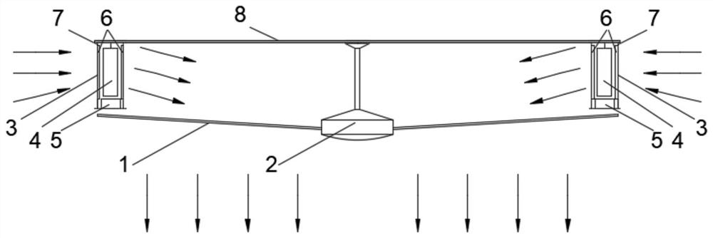
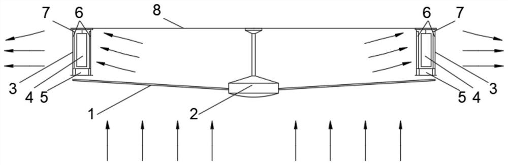
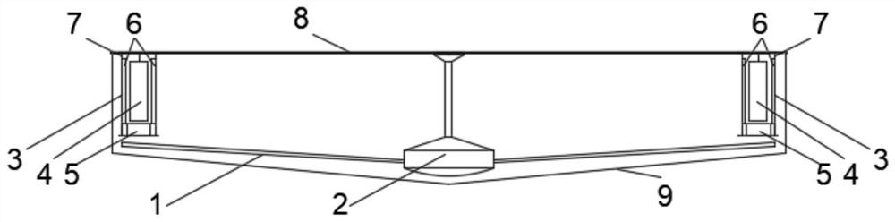
[0029] See Figure 1 - Figure 4 A device of a ceiling fan coupled air conditioner system, including a hanging sector unit including a base 8, a fan blade 1, and a hanger motor 2 that enables forward inversion, where the number of the blanks 1 is at least greater than 2 pieces, through a conventional method Installing on the ceiling fan motor 2, the ceiling fan is mounted at the center position of the disc shaped base 8, and the outer edge of the base 8 can also be installed a hanging sector cover, reducing dust accumulation (eg image 3 and 4 Indicated by it);

[0030] Air conditioning unit includes an annular casing 7, a heat exchanger assembly 4, and a condensate disk 5, wherein the outer side of the housing 7 is uniformly disposed in the outer side, and the number of air outlets is at least 3, and The inner and outer air port 3 corresponds, and low resistance coarse effect filter 6 is mounted on both side air port 3, which is used to filter the large dust in the ventilation of th...

Embodiment 2

[0033] See Figure 5 A device for a ceiling fan coupled air conditioning system, wherein the base 8 is a quadrilateral, the casing 7 of the air conditioner unit and the condensate disk 5 are four-side annular structure, and the number of air outlets on both sides of the casing 7 are at least 4, change The heat assembly 4 is a four-side annular heat exchanger, and the rest is the same as in Example 1.


PUM


Abstract

The invention relates to the technical field of air conditioners, in particular to a ceiling fan coupling air conditioning system device. The ceiling fan comprises a base, fan blades, a ceiling fan motor capable of achieving forward and reverse rotation, an annular shell provided with an air opening, a heat exchanger assembly and a condensate water disc, a low-resistance coarse-efficiency filter screen is installed at the air opening and used for filtering large dust in return air of a ceiling fan unit and reducing particulate matter attached to the surface of a heat exchanger, and the interior of the annular shell is of a cavity structure. The annular heat exchanger assembly is fixedly arranged in a cavity of the annular shell and used for heat exchange, the condensate water disc is arranged at the bottom of the annular shell and externally connected with a water pump for water drainage, the occupied space is small, a centrifugal air feeder of an air conditioner unit is omitted, the air conditioner unit is driven by a low-power ceiling fan to exchange heat, and energy consumption of the fan is reduced. Air conditioner air supply uniformity is improved through large-area air supply of the ceiling fan unit, and regional temperature difference nonuniformity of indoor personnel is reduced.

Description

Technical field [0001] The present invention relates to the field of air conditioning, in particular, a device for a ceiling or coupling air conditioning system. Background technique [0002] At present, residential buildings and public buildings are mainly adjusted by air conditioning, including split air conditioners or central air conditioning air conditioning systems. In addition, most buildings also install a ceiling fan to meet the hot comfort of the summer temperature. The air conditioner includes a heat exchanger and a blower. When the weather is hot or cold, the indoor temperature can be adjusted by the heat exchanger to the appropriate state. The main function of the fan is to form a wind gas stream, which cannot achieve cooling or heating function. However, when the room temperature is low, the air is creating air to streaming heat transfer, which is in a comfortable state. Thus, there is often an air conditioning and a fan internally installed inside the residential b...

Claims


Application Information

Patent Timeline
Patent Type & Authority Applications(China)
IPC IPC(8): F24F1/0022F24F1/0047F24F1/0073F24F8/108F24F11/65F24F11/72F24F11/88F24F13/06F24F13/22F04D25/08
CPCF24F1/0022F24F1/0047F24F1/0073F24F8/108F24F11/65F24F11/72F24F11/88F24F13/06F24F13/22F04D25/088
Inventor 陈文华彭效靳树蕊朱雪燕孙小月彭冬根郭兴国
Owner NANCHANG UNIV
Why Eureka
Try Eureka