
Vacuum type low-temperature control needle valve

A vacuum-type, low-temperature technology, applied in the field of vacuum-type low-temperature control needle valves, can solve the problems of large leakage heat loss, freezing control operation rods, and poor sealing, so as to improve sealing performance, improve heat insulation effect, and reduce leakage. effect of heat loss

Pending Publication Date: 2022-03-11
深圳市福田区南科大量子技术与工程研究院
View PDF0 Cites 0 Cited by
  • Summary
  • Abstract
  • Description
  • Claims
  • Application Information

AI Technical Summary

Problems solved by technology

Most of the existing flow control needle valves are composed of a control operating rod, a needle valve seat and a flow control needle. Although the structure is relatively simple, many problems are often encountered in use. For example, the control operating rod does not have a good Heat insulation measures, which result in greater heat loss during liquid transmission; in addition, because the control lever and the fixed seat are often not tightly sealed, resulting in a small amount of air entering and causing ice to freeze the control joystick problem

Method used


Image

  • Vacuum type low-temperature control needle valve
  • Vacuum type low-temperature control needle valve
  • Vacuum type low-temperature control needle valve

Examples


Embodiment Construction

[0023] The technical solutions of the present invention will be clearly and completely described below with reference to the accompanying drawings. Obviously, the described embodiments are part of the embodiments of the present invention, but not all of the embodiments. Based on the embodiments of the present invention, all other embodiments obtained by those of ordinary skill in the art without creative efforts shall fall within the protection scope of the present invention.

[0024] In the description of the present invention, it should be noted that the terms "center", "upper", "lower", "left", "right", "vertical", "horizontal", "inner", "outer", etc. The indicated orientation or positional relationship is based on the orientation or positional relationship shown in the accompanying drawings, which is only for the convenience of describing the present invention and simplifying the description, rather than indicating or implying that the indicated device or element must have ...


PUM


Abstract

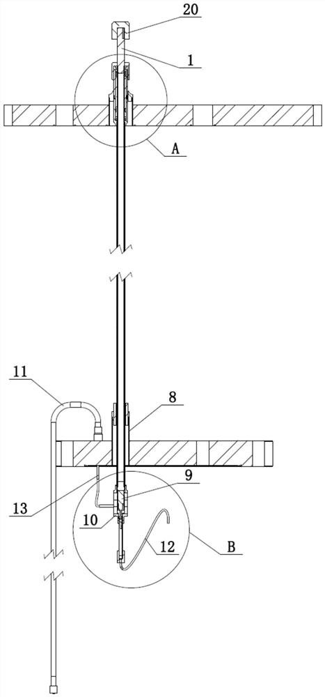
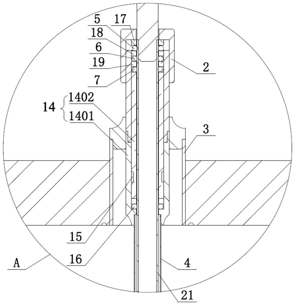
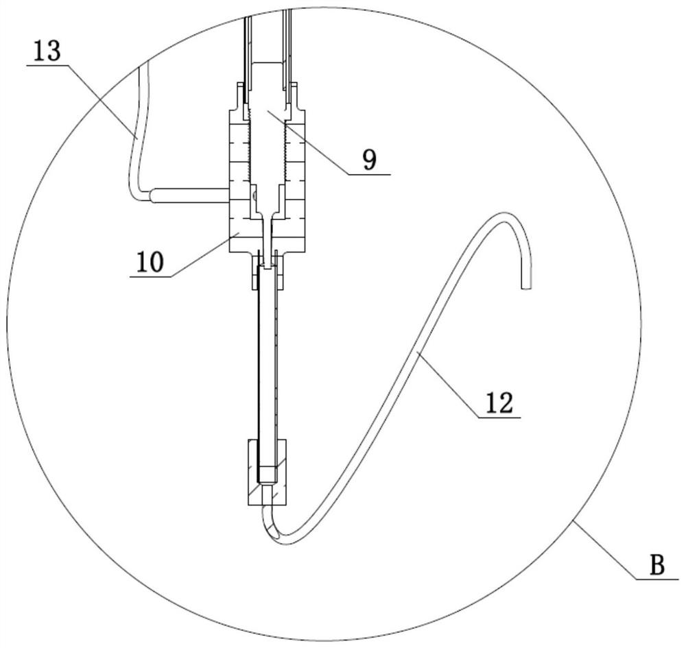
The invention discloses a vacuum type low-temperature control needle valve, and belongs to the technical field of fluid transmission control in a low-temperature system. The vacuum type low-temperature control needle valve comprises an operating rod, a control connecting pipe, a fixing seat, a sleeve, a room-temperature mounting seat, a heat insulation outer pipe, a first sealing ring, a second sealing ring, a third sealing ring, a flow control needle, a valve body, a vacuum liquid suction capillary tube, a liquid output pipe and a vacuum interlayer. According to the vacuum type low-temperature control needle valve, the heat insulation vacuum interlayer is arranged outside the vacuum liquid suction capillary tube in a sleeving mode, so that heat leakage loss in the liquid conveying process is reduced to a great extent, the heat insulation outer tube is arranged on the control connecting tube in a sleeving mode, and three sealing rings are connected between the control connecting tube and the fixing base in a sealed mode, so that the heat leakage loss is reduced to a great extent. The heat insulation effect is further improved, the sealing performance is improved, and the phenomenon that due to untight sealing, a little air enters the vacuum type low-temperature control needle valve, and consequently the operating rod and the control connecting pipe are frozen is avoided.

Description

technical field [0001] The invention relates to the technical field of fluid transmission control in a cryogenic system, in particular to a vacuum type cryogenic control needle valve. Background technique [0002] In cryogenic refrigeration systems there is often a need to transport liquids into containers, such as transport and control 4 He (helium 4) or 3 In the case of He (helium 3) fluid, etc., a valve device with flow control is required at this time, and the most commonly used is the flow control needle valve. The existing flow control needle valve is mostly composed of a control operating rod, a needle valve seat and a flow control needle. Although its structure is relatively simple, it often encounters many problems in use. For example, the control operating rod does not have a good Insulation measures, which result in a larger loss of heat leakage during the liquid transmission process; in addition, because the sealing between the control lever and the fixed seat ...

Claims


Application Information

Patent Timeline
IPC IPC(8): F16K1/02F16K1/32F16K1/38F16K27/02F16K31/04F16K31/50F16K31/60F16K41/04F16L59/065
CPCF16K1/02F16K1/32F16K1/38F16K27/0254F16K31/04F16K31/50F16K31/60F16K41/04F16L59/065
Inventor 付柏山韩旭东俞大鹏
Owner 深圳市福田区南科大量子技术与工程研究院
Learn More