Eureka AIR delivers breakthrough ideas for toughest innovation challenges, trusted by R&D personnel around the world.

Potential energy wave function domain seismic data quality factor estimation method

A technology of quality factor and seismic data, applied in the field of geophysical processing of oil and gas exploration, can solve the problems of affecting accuracy, cumbersome, difficult amplitude information, etc., to achieve the effect of fast operation and improved accuracy

Active Publication Date: 2022-03-08
CHENGDU UNIV OF INFORMATION TECH
View PDF6 Cites 0 Cited by
  • Summary
  • Abstract
  • Description
  • Claims
  • Application Information

AI Technical Summary

Problems solved by technology

Time-domain Q estimation methods, such as rise time method and amplitude decay method, require real amplitude information, but due to the influence of wavefront expansion and transmission loss, it is difficult to obtain real amplitude information from actual seismic data
Frequency domain Q estimation methods such as spectral ratio method, peak frequency offset method, etc., the main difficulty is that there is spectral interference between adjacent reflections, and it is necessary to select an appropriate frequency band for Q estimation. The Q values ​​estimated by different frequency bands are quite different. The spectral fluctuations present in , make selecting an appropriate frequency band a very tedious task, and such methods are sensitive to noise
The time-frequency domain Q estimation method reduces the spectral interference and other problems existing in the frequency domain Q estimation method, although the characteristics of different time-frequency analysis methods will also affect the accuracy of Q estimation, using variable window time-frequency analysis methods such as wavelet transform It has been proved that the time-frequency analysis method using a fixed window, such as the short-time Fourier transform, can give a more robust and accurate Q estimate, but there is still the problem of selecting an appropriate frequency band for Q estimation

Method used


Image

  • Potential energy wave function domain seismic data quality factor estimation method
  • Potential energy wave function domain seismic data quality factor estimation method
  • Potential energy wave function domain seismic data quality factor estimation method

Examples


Embodiment Construction

[0052] (1) figure 1 It is the seismic synthetic record used for formation quality factor calculation. Seismic synthetic records were generated using minimum phase wavelets, with a theoretical quality factor of 30 and a sampling frequency of 500 Hz.

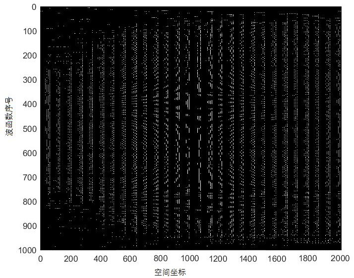
[0053] (2) figure 2 Shown for the potential-wavefunction domain wavefunction. Planck's constant is taken as 1. A total of 2000 wave functions were generated from the synthetic seismogram.

[0054] (3) image 3 Maps the signal to the potential-wavefunction domain of the raw seismic signal.

[0055] (4) Figure 4 is the fitted curve for Q estimation using this technique. The least squares method was used to fit the logarithmic mapping sequence within the preferred range, the slope of the fitted line obtained was 5.7497, and the calculated Q value was 26.

[0056] (5) Figure 5 To estimate Q for this seismic record using the conventional spectral ratio method. (a) The time-frequency spectrum of the seismic record. (b)...


PUM


Abstract

The invention belongs to the field of geophysical processing methods for oil-gas exploration. The invention discloses a potential energy wave function domain seismic data quality factor estimation method. The method comprises the following steps: decomposing seismic data of a target area in a potential energy-wave function domain by using a Schrodinger equation of non-relativistic quantum mechanics, constructing an adaptive basis function through a Hamiltonian matrix, and calculating a mapping coefficient sequence of the seismic data in a potential energy-wave function space channel by channel; and calculating the Q estimation result of the adjacent horizon by using the mapping coefficient sequence of the potential energy-wave function space in combination with a least square method. The invention provides a seismic signal self-adaptive decomposition algorithm based on a quantum mechanics Schrodinger equation, derives a potential energy-wave function domain Q estimation algorithm, develops a high-precision potential energy-wave function domain seismic data Q estimation method, improves the accuracy of Q estimation, and provides a seismic signal self-adaptive decomposition algorithm based on a quantum mechanics Schrodinger equation. The problems that a traditional Q estimation method needs to select a frequency band and various assumption preconditions exist are solved.

Description

technical field [0001] The invention relates to the field of geophysical processing methods for oil and gas exploration, in particular to a method for estimating the quality factor of seismic data using the principle of quantum mechanics. Background technique [0002] The attenuation of seismic waves originates from the anelastic process that occurs during propagation. Attenuation can usually be divided into two parts, apparent loss and intrinsic loss. Apparent loss includes energy loss caused by processes such as formation disturbance and scattering effects and some resonance phenomena, while intrinsic loss mainly comes from energy loss caused by converting seismic energy into thermal energy and fluid flow. Apparent losses are related to media properties such as delamination and impedance contrast, while intrinsic losses are related to media properties such as fluid content, permeability and viscosity. This intrinsic medium property, which causes seismic wave amplitude at...

Claims


Application Information

Patent Timeline
Patent Type & Authority Applications(China)
IPC IPC(8): G01V1/28G01V1/30G06F17/11G06F17/15G06N10/60
CPCG01V1/28G01V1/306G06F17/11G06F17/15G06N10/00G01V2210/61G01V2210/6169G01V2210/624
Inventor 薛雅娟曹俊兴王兴建杜浩坤周娟杨佳文展
Owner CHENGDU UNIV OF INFORMATION TECH
Why Eureka
Eureka Blog
Learn More