
Lateral steam admission condenser tube bundle

A condenser and steam inlet technology, which is applied to steam/steam condensers, lighting and heating equipment, etc., can solve the problem of increased investment in side steam inlet condensers, unsatisfactory heat transfer coefficient, and excessive shell side flow resistance and other problems, to achieve obvious energy-saving effect, easy pipe installation, and no eddy current in the flow field

Pending Publication Date: 2022-03-08
广州海恩能源技术有限公司
View PDF0 Cites 0 Cited by
  • Summary
  • Abstract
  • Description
  • Claims
  • Application Information

AI Technical Summary

Problems solved by technology

[0004] The existing domestic side-inlet condenser pipe layout is less, more or less there are problems such as excessive flow resistance on the shell side and large subcooling degree, and the actual heat transfer coefficient is not ideal
However, most of the existing bottom exhaust steam condensers are not compact enough. If they are directly inverted and used for side steam inlet condensers, the investment of side steam inlet condensers will increase significantly.

Method used


Image

  • Lateral steam admission condenser tube bundle
  • Lateral steam admission condenser tube bundle
  • Lateral steam admission condenser tube bundle

Examples


Embodiment 1

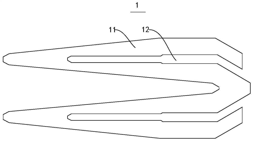
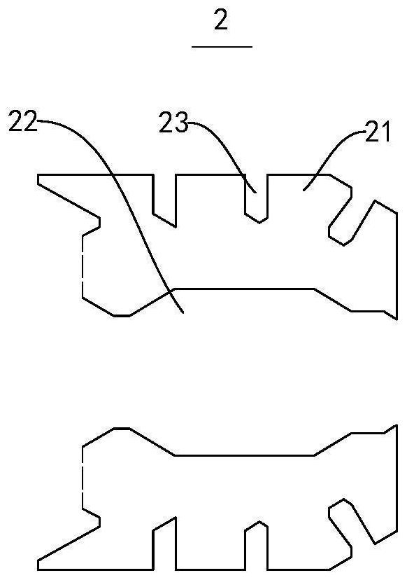
[0031] Please refer to Figure 1 to Figure 4 , this embodiment provides a side inlet condenser tube bundle, the side inlet condenser adopts side inlet, and the exhaust steam discharged from the low pressure cylinder of the steam turbine flows horizontally in the inner cavity of the condenser, this embodiment It includes a number of heat exchange tubes, and several heat exchange tubes are arranged to form the front tube bundle area 1, the rear tube bundle area 2 and the air-cooled tube bundle area 3. The heat exchange tube constitutes a specific shape, such as Figure 5 As shown, the front-end tube bundle area 1, the rear-end tube bundle area 2 and the air-cooled tube bundle area 3 are sequentially arranged in the inner cavity of the condenser along the exhaust direction of the condenser. Specifically, the tube bundle of the air-cooled tube bundle area 3 occupies the entire tube bundle The percentage of the total quantity is 5%-7%; the air-cooled tube bundle area 3 is equipped...


PUM


Abstract

The invention provides a lateral steam admission condenser tube bundle which comprises a plurality of heat exchange tubes, the heat exchange tubes form a front-end tube bundle area, a rear-end tube bundle area and an air cooling tube bundle area, the front-end tube bundle area, the rear-end tube bundle area and the air cooling tube bundle area are sequentially arranged in an inner cavity of a condenser in the exhaust direction of the condenser, and the air cooling tube bundle area is provided with an air extraction opening. The front-end tube bundle area is provided with a front middle steam channel in the exhaust direction of the condenser, the rear-end tube bundle area is provided with a rear middle steam channel in the exhaust direction of the condenser, the front middle steam channel is communicated with the rear middle steam channel, and the air cooling tube bundle area is located at the tail end of the rear middle steam channel. The structure is compact, investment of a power plant is saved, meanwhile, a tube bundle steam flow field is uniform and free of vortex, shell side steam resistance is small, heat load distribution is uniform, the steam condensation rate is high, and the heat transfer coefficient and the operation vacuum degree of the condenser are high.

Description

technical field [0001] The invention relates to the technical field of heat exchangers, in particular to a side steam inlet condenser tube bundle. Background technique [0002] The side inlet steam condenser is a shell-and-tube heat exchanger, which is an important component of the gas-steam combined cycle unit. Its function is to condense the exhaust steam discharged from the low-pressure cylinder of the steam turbine into water and put it Establish and maintain a certain vacuum value. The rationality of the cooling tube bundle arrangement of the condenser has an important impact on the steam condensation process, and has a greater impact on its heat transfer performance and energy consumption of the unit. Unreasonable arrangement of tube bundles will lead to unreasonable steam flow field, resulting in uneven distribution of heat load, local air accumulation, excessive flow resistance, high degree of subcooling, and air leakage (uncondensed steam directly enters the air co...

Claims


Application Information

Patent Timeline
Patent Type & Authority Applications(China)
IPC IPC(8): F28B1/02F28B1/06F28B9/00F28B9/08F28B9/10
CPCF28B1/02F28B1/06F28B9/00F28B9/08F28B9/10
Inventor 黄文兵刘洋
Owner 广州海恩能源技术有限公司
Learn More