
Hollow fiber membrane module, and a manufacturing method therefor, and housing for hollow fiber membrane module

a technology manufacturing method, which is applied in the direction of light beam reproducing, instruments, transportation and packaging, etc., can solve the problems of low thickness of hollow fiber membrane module per unit volume, restricted longitudinal direction of hollow fiber membrane bundle deflection in the housing, and high contaminated water hair accumulation, etc., to achieve easy pouring of fixing resin into the resin pouring section, the effect of reducing the consumed amount of the necessary fixing resin

Inactive Publication Date: 2008-07-10
MITSUBISHI RAYON CO LTD
View PDF10 Cites 2 Cited by
  • Summary
  • Abstract
  • Description
  • Claims
  • Application Information

AI Technical Summary

Benefits of technology

This design increases the integration ratio of the hollow fiber membrane module, minimizes deflection and entanglement, and enhances mechanical strength and anti-pressure characteristics, resulting in improved durability and efficiency during filtration processes.

Problems solved by technology

However, in such a method, it is necessary to use a housing having a large diameter because it is necessary to insert a cutter in the housing.
Therefore, there is a problem in that an integration of the hollow fiber membrane module per a unit volume is low in a hollow fiber membrane module unit when a plurality of the hollow fiber membrane modules are integrated so as to assemble the hollow fiber membrane module unit.
Also, there are problems in that the hollow fiber membrane module 11 is broken, crumbs and a hair contained in the highly contaminated water accumulates, and a uniform air bubbling operation is not realized because of such an entanglement of the hollow fiber membrane bundle 14 when the hollow fiber membrane module unit is used for a long time.
However, a method in which a deflection in the housing in the longitudinal direction of the hollow fiber membrane bundle is restricted so as to prevent the entanglement of the hollow fiber membrane has not been proposed specifically.
Also, it is not easy to apply the bonding agent to the end caps 17, 18; therefore, there is a problem in that a production efficiency decreases.
In such cases, it is not possible to obtain a sufficient capacity in the pouring section 25.
Furthermore, sufficient amount of the resin is not used in a potting operation; thus, the fixing resin 15 does not prevail entirely; therefore, a product has a defect.
Also, there is a concern for an anti-pressure characteristics and durability because of insufficiency of the potting resin.

Method used


Image

  • Hollow fiber membrane module, and a manufacturing method therefor, and housing for hollow fiber membrane module
  • Hollow fiber membrane module, and a manufacturing method therefor, and housing for hollow fiber membrane module
  • Hollow fiber membrane module, and a manufacturing method therefor, and housing for hollow fiber membrane module

Examples


Embodiment Construction

[0079]Here, the present invention is further explained in detail.

First Aspect of the Hollow Fiber Membrane Module

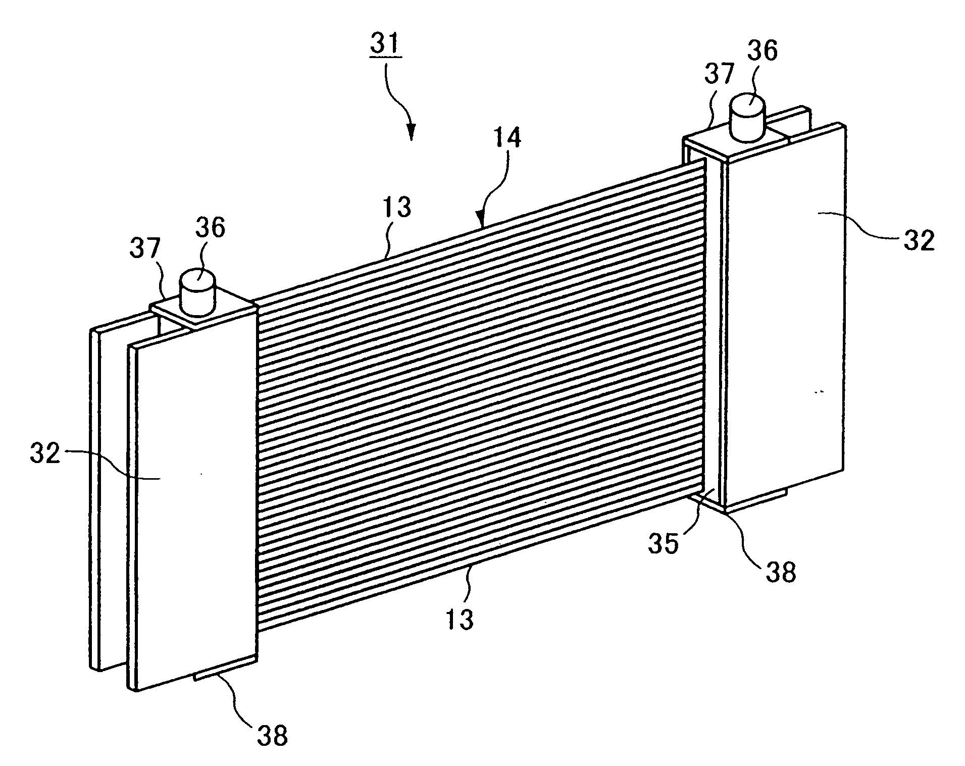
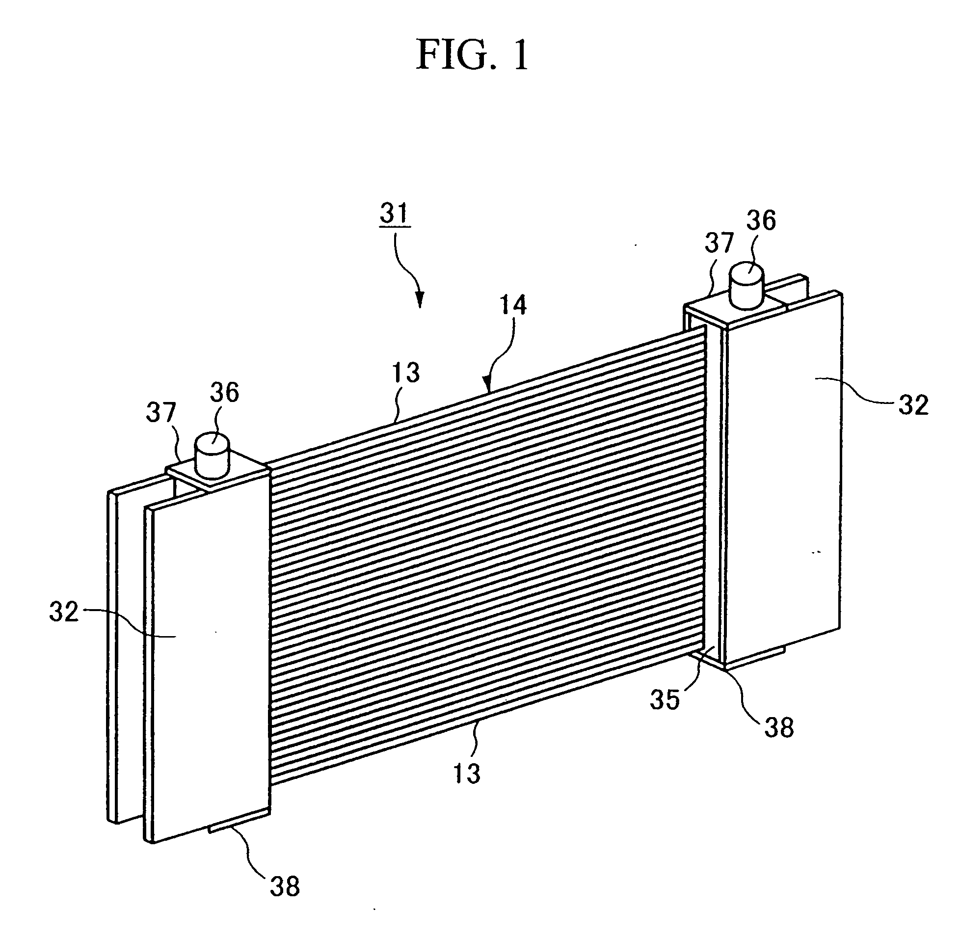
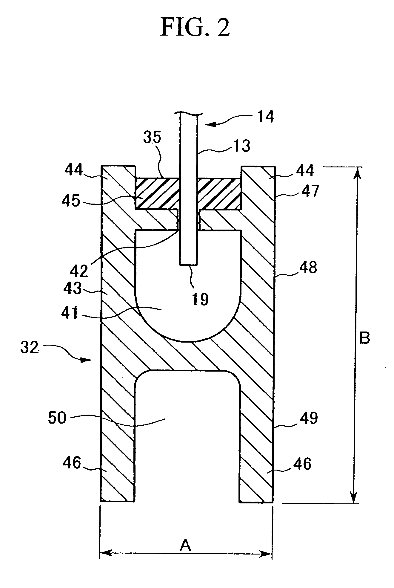
[0080]FIG. 1 is a perspective view showing an example for a hollow fiber membrane module according to the present invention. FIG. 2 is a cross section in the housing in the hollow fiber membrane module shown in FIG. 1.

[0081]A hollow fiber membrane module 31 approximately comprises a pair of housings 32, a hollow fiber membrane bundle 14 in which a plurality of hollow fiber membranes 13 are bundled as a sheet, an end cap 37 which is attached on an end of the housing 32 having a processed-water exit 36, and an end cap 38 which is attached on another end of the housing 32 without a processed-water exit. Here, the hollow fiber membrane bundle 14 is fixed on the housing 32 by the fixing resin 35 under condition that the hollow fiber membrane bundle 14 is inserted in the housing 32 and an opening end section 19 in the hollow fiber membranes 19 is maintained open.

[0082]The housi...


PUM

PropertyMeasurementUnit
thicknessaaaaaaaaaa
widthaaaaaaaaaa
widthaaaaaaaaaa

Abstract

In a hollow fiber membrane flat module according to the present invention, both ends of hollow fiber membrane bundle which are formed by bundling a plurality of hollow fiber membrane as a sheet are fixed to two housing separately by a fixing resin while maintaining an opening condition in an opening end section in the follow fiber membrane. Furthermore, a maximum width in an orthogonal direction to a longitudinal direction of the hollow fiber membrane is no longer than 25 mm in a cross section which is orthogonal to a longitudinal direction of the housings, and a maximum deflection in the housings which are measured according to a method for measuring the deflection according to the present invention is not more than 1% of a distance between the two housings. In such a hollow fiber membrane module, it is possible to enhance the integration ratio of the hollow fiber membrane module per a unit volume of the hollow fiber membrane module unit in which there is less deflections in the housing caused by adjust the wavelength dispersion and the dispersion slope always in minimum level automatically only by matching the position of the reflecting mirror 8, the dispersion compensation amount and the dispersion slope compensation amount which correspond to a shape of the reflecting surface 8a on the reflecting mirror 8 which is selected under such a current condition in advance. Factors such as an air bubble, and the entanglement of the hollow fiber membranes is restricted; thus, a hollow fiber membrane is not damaged. Also, in the hollow fiber membrane module, it is preferable that the housing is provided with a reinforcing rib section which strengthens the housing.

Description

CROSS-REFERENCE TO RELATED APPLICATIONS[0001]This is a continuation of U.S. application Ser. No. 10 / 450,659, filed Jun. 16, 2003, which is a U.S. National Phase of International Application PCT / JP01 / 11034, filed Dec. 17, 2001, and claims the benefit of priority under 35 U.S.C. § 119 of Japanese Applications 2000-383556, filed Dec. 18, 2000; 2001-000562 filed Jan. 5, 2001; 2001-028343, filed Feb. 5, 2001; and 2001-072857, filed Mar. 14, 2001, the entire disclosures of which are hereby incorporated herein by reference.TECHNICAL FIELD[0002]The present invention relates to a hollow fiber membrane module, a method for manufacturing therefore, and a hollow fiber membrane module housing which are used for separating and refining a liquid member.BACKGROUND ART[0003]Conventionally, a hollow fiber membrane module has been used for a lot of purposes such as manufacturing an axenic water, drinking water, and highly pure water, and cleaning an atmosphere. In addition to these purposes, in recent...

Claims


Application Information

Patent Timeline
Patent Type & Authority Applications(United States)
IPC IPC(8): B32B9/04B01D63/02B01D63/04
CPCB01D63/02B01D63/021B01D63/022Y10T428/26B01D63/043B01D63/026B01D63/024Y10T428/31504B01D63/0233B01D63/031B01D63/0241B01D63/04
Inventor NAKAHARA, YOSHIHITOTORICHIGAI, TETSUYAKAMATA, MASATOSHIITO, MASANORIHONJOU, KENJIOKAZAKI, HIROYUKIKAKUMOTO, YOSHIHIRO
Owner MITSUBISHI RAYON CO LTD
Learn More