
Combustion lubricating oil heat management and anti-icing comprehensive control system of gas turbine engine

A gas turbine and comprehensive control technology, applied in the direction of turbine/propulsion fuel delivery system, engine lubrication, gas turbine device, etc., can solve the problems of low air enthalpy, high heating power, serious fuel temperature rise, etc., and achieve easy implementation and high efficiency. Integrated, easily modifiable effects

Pending Publication Date: 2022-03-08
AECC SICHUAN GAS TURBINE RES INST
View PDF17 Cites 0 Cited by
  • Summary
  • Abstract
  • Description
  • Claims
  • Application Information

AI Technical Summary

Problems solved by technology

[0002] In the future, the high-thrust and high-Mach number aero-engine will have a large number of on-board equipment and high heating power. At the same time, in order to improve the stealth performance of the aircraft, the openings on the surface of the aircraft are restricted to reduce the intake area of ​​ram air. Therefore, traditional air circulation is adopted. Cooling can no longer meet cooling needs
In addition, in order to meet the requirements of the thrust system, the flow rate of the engine fuel pump is about 70% higher than that of the third-generation engine, which leads to serious fuel temperature rise in the working condition of low fuel consumption
Therefore, fighter planes powered by engines are faced with the problem that the system generates serious heat, but the heat dissipation cannot meet the demand; at the same time, during the climb and return process of the aircraft, they face the problem of freezing of the rectifier struts and cowls at the inlet of the engine. The ice system usually introduces hot air from the outlet of the compression parts to heat the engine inlet rectifying strut and cowl to prevent the surface from icing and ensure the normal function of the rectifying strut and cowl. However, the enthalpy of the air is very low, and a large amount of airflow needs to be introduced from the main flow of the engine. , resulting in reduced engine performance

Method used


Image

  • Combustion lubricating oil heat management and anti-icing comprehensive control system of gas turbine engine
  • Combustion lubricating oil heat management and anti-icing comprehensive control system of gas turbine engine
  • Combustion lubricating oil heat management and anti-icing comprehensive control system of gas turbine engine

Examples


Embodiment Construction

[0026] Embodiments of the present disclosure will be described in detail below in conjunction with the accompanying drawings.

[0027] Embodiments of the present disclosure are described below through specific examples, and those skilled in the art can easily understand other advantages and effects of the present disclosure from the content disclosed in this specification. Apparently, the described embodiments are only some of the embodiments of the present disclosure, not all of them. The present disclosure can also be implemented or applied through different specific implementation modes, and various modifications or changes can be made to the details in this specification based on different viewpoints and applications without departing from the spirit of the present disclosure. It should be noted that, in the case of no conflict, the following embodiments and features in the embodiments can be combined with each other. Based on the embodiments in the present disclosure, al...


PUM


Abstract

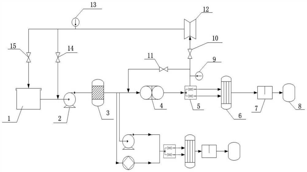
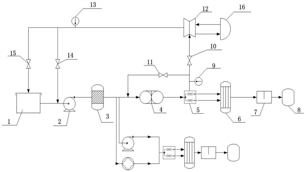
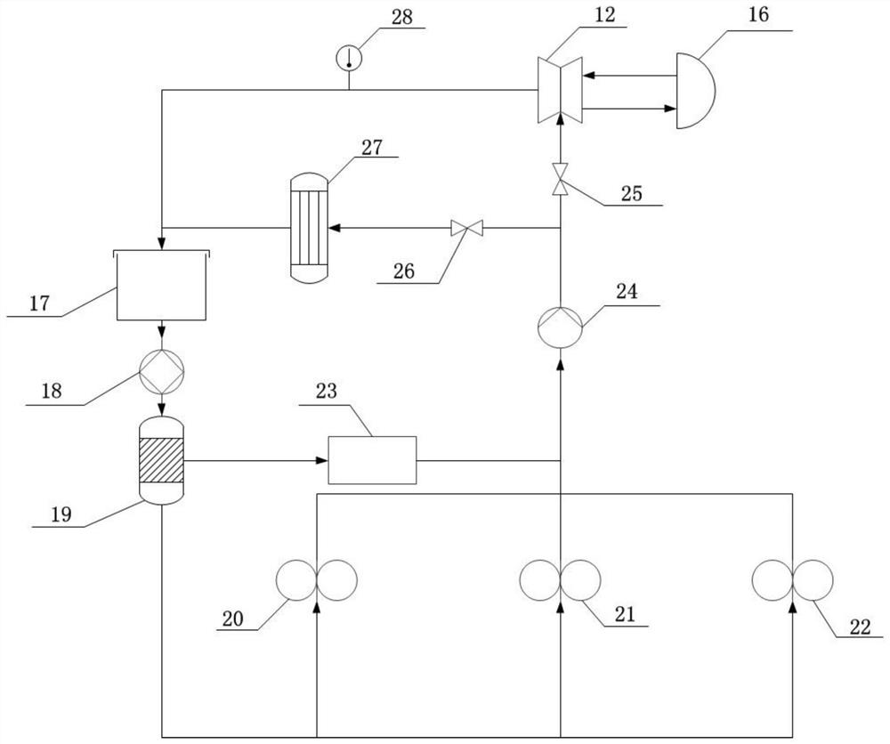
The invention provides a gas turbine engine fuel oil and lubricating oil thermal management and anti-icing comprehensive control system which comprises a main fuel oil system, a lubricating oil system, an engine inlet rectification supporting plate and a control system, the main fuel oil system further comprises a first valve, the first output end of a main fuel oil regulator is connected with the engine inlet rectification supporting plate, and the second output end of the main fuel oil regulator is connected with the control system. The first valve is arranged on the connecting pipeline; the lubricating oil system further comprises a second valve, the first output end of the lubricating oil scavenging pump is connected with the engine inlet rectifying supporting plate, the second valve is arranged on a connecting pipeline, and the first valve and the second valve are both connected with the control system. While heat dissipation and anti-icing requirements of a heat management system are met, heat sink of an engine system is fully excavated, and anti-icing bleed air of the engine is reduced.

Description

technical field [0001] The disclosure relates to the technical field of aero-engines, in particular to a gas turbine engine combustion oil thermal management and anti-icing integrated control system. Background technique [0002] In the future, the high-thrust and high-Mach number aero-engine will have a large number of on-board equipment and high heating power. At the same time, in order to improve the stealth performance of the aircraft, the openings on the surface of the aircraft are restricted to reduce the intake area of ​​ram air. Therefore, traditional air circulation is adopted. Cooling can no longer meet cooling needs. In addition, in order to meet the requirements of the thrust system, the flow rate of the engine fuel pump is about 70% higher than that of the third-generation engine, which leads to serious fuel temperature rise in the working condition of low fuel consumption. Therefore, fighter planes powered by engines are faced with the problem that the system ...

Claims


Application Information

Patent Timeline
IPC IPC(8): F01D25/10F01D25/12F02C7/06F02C7/141F02C7/224
CPCF01D25/12F01D25/10F02C7/141F02C7/224F02C7/06
Inventor 周雷陈胜广马庆辉魏俊杰
Owner AECC SICHUAN GAS TURBINE RES INST
Learn More