
Ultrasonic milling device

A milling device and ultrasonic technology, applied in the field of milling, can solve problems such as bad conditions, increased volume, and weak rigidity

Active Publication Date: 2022-03-08
HANGZHOU SUCCESS ULTRASONIC EQUIP
View PDF8 Cites 0 Cited by
  • Summary
  • Abstract
  • Description
  • Claims
  • Application Information

AI Technical Summary

Problems solved by technology

However, if the horn is added in milling, it will reduce the industrial applicability. First, the horn must be designed to be multiplied and lengthened according to the ultrasonic characteristics. Then the volume of the high-speed rotating part of the milling device will increase, which is inconvenient to install and is not conducive to its high speed. Rotation, moreover, the existence of the horn will greatly weaken the overall rigidity, in addition, the power of the transducer with torsional vibration or bending vibration is significantly smaller
[0005] The patent application No. 20140752599.4 solves the above problems to a certain extent, but there are still the following problems: First, the ultrasonic transducer cannot dissipate heat due to heat after working for a long time, and burns out
Second, when the transducer is damaged and needs to be replaced, remove the wires and rotate the upper tightening ring on the lower side to remove it, which is very inconvenient to replace
Third, the carbon brush is used for power supply. After long-term use, the carbon brush wears out. Because of the limited length of the spring layout space, after the wear, the force generated by the deformation of the spring is relatively large. The pressure of the ring piece is reduced, which is prone to adverse conditions

Method used


Image

  • Ultrasonic milling device
  • Ultrasonic milling device
  • Ultrasonic milling device

Examples


Embodiment approach

[0060] Embodiment: When using the device designed by the present invention, after the carbon brush rod 51 is worn for a long time, the pressure of the two third springs 48 on both sides will also change accordingly, so as to ensure that the carbon brush rod 51 on both sides is in contact with the positive pole. The ring 42 and the negative electrode ring 40 are in close contact, because the third spring 48 designed by the present invention tightens the carbon brush rod 51 from both sides, compared with the existing spring extruded at the rear side of the carbon brush rod 51, this The length of space that the third spring 48 can be arranged in the invention is far greater than the existing one, that is, the third spring 48 can have a longer pre-compression amount. The amount of pre-compression is very small, so when the change of the spring pre-pressure is relatively small after wear, the change of the extrusion force of the carbon brush rod 51 on the positive electrode ring 42 ...


PUM


Abstract

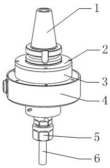
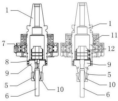
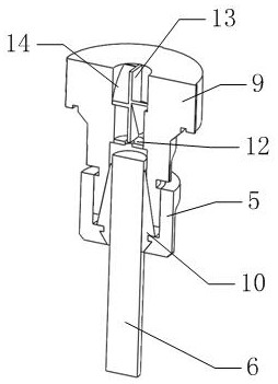
The invention belongs to the technical field of milling, and particularly relates to an ultrasonic milling device. The device comprises a cutter body, a first flange plate, a bearing sleeve, a mounting sleeve, a locking nut, a cutter, an aviation plug, a lower tightening plate, an upper tightening plate, an elastic chuck, a bearing, a second flange plate, a power supply device, a negative electrode ring, a first electrode isolating ring, a positive electrode ring, a second electrode isolating ring, a fastening cap, a carbon brush mechanism and an ultrasonic transducer. After the carbon brush rods are abraded, the abrasion loss of the carbon brush rods is very small relative to the pre-compression amount of the third springs, so that the change of the pre-compression amount of the springs is relatively small after the carbon brush rods are abraded, and the carbon brush rods are ensured to be tightly contacted with the positive pole ring and the negative pole ring. The extrusion force of the carbon brush rod on the positive pole ring and the negative pole ring is relatively small in change, and enough extrusion force can be ensured after abrasion.

Description

technical field [0001] The invention belongs to the technical field of milling, in particular to an ultrasonic milling device. Background technique [0002] CNC lathes can process complex rotary shapes. Milling is to fix the blank, and use a high-speed rotating milling cutter to move on the blank to cut out the required shape and features. Traditional milling is mostly used for simple shape features such as milling contours and slots. CNC milling machines can process complex shapes and features. The milling and boring machining center can perform three-axis or multi-axis milling and boring, which is used for machining, molds, inspection tools, molds, thin-walled complex surfaces, artificial prostheses, blades, etc. [0003] With the development of milling technology, the requirements for the rotation speed of the spindle are getting higher and higher. With the development of ultrasonic power supply technology, ultrasonic milling, which combines high-frequency ultrasonic v...

Claims


Application Information

Patent Timeline
Patent Type & Authority Applications(China)
IPC IPC(8): B23C9/00B23Q3/00B23Q11/12
CPCB23C9/00B23Q3/00B23Q11/12
Inventor 陈川陈元平
Owner HANGZHOU SUCCESS ULTRASONIC EQUIP
Learn More