Main beam deflection monitoring device based on binocular vision and monitoring method thereof

A monitoring device and a technology for deflection of the main girder, which is applied in the field of cranes, can solve the problems of inward bending, inability to monitor deflection, time-consuming and labor-intensive problems, and achieve the effect of real-time deformation

Pending Publication Date: 2022-03-04
FUJIAN SPECIAL EQUIP TESTING RES INST
View PDF8 Cites 2 Cited by
  • Summary
  • Abstract
  • Description
  • Claims
  • Application Information

AI Technical Summary

Problems solved by technology

[0002] In order to ensure the safe use of the crane, the deflection of the main girder of the crane needs to be detected during the use of the crane to ensure that the deflection is within a safe range. The traditional method uses methods such as wire drawing measurement method, theodolite method, level method, and connector method to measure manually. Not only time-consuming and labor-intensive but also affected by human factors
For this reason, two improvement schemes have been proposed in the prior art. One is to use the image visual sensing method to regularly detect the deflection of the main girder. One method is to use a laser range finder to detect the change of the distance between the main beam and the ground. The disadvantage is that it can only detect the deflection change under ideal conditions. In the actual working process, the main beam of the crane is bent downward, Inward bending will also occur, and this method cannot detect this change. Therefore, it is necessary to propose a monitoring method that can detect the vertical and horizontal bending degree of the main beam in real time

Method used


Image

  • Main beam deflection monitoring device based on binocular vision and monitoring method thereof
  • Main beam deflection monitoring device based on binocular vision and monitoring method thereof
  • Main beam deflection monitoring device based on binocular vision and monitoring method thereof

Examples


Embodiment 1

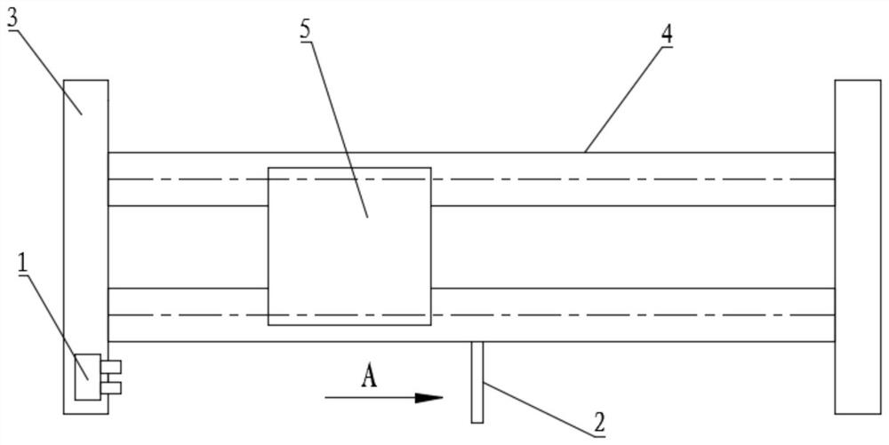
[0058] Please refer to figure 1 , the crane girder deflection online monitoring device of the present embodiment is suitable for on-line detection of the girder 4 deflection of the gantry crane, which includes a binocular camera 1 and a target 2, wherein the binocular camera 1 is composed of a left camera and a right camera, They are all set on the end beam 3 on one side of the crane, and the target 2 is located on any one of the two main beams 4 of the gantry crane. Due to the stress distribution, usually the most deformed part of the main beam 4 is located in the middle of the main beam 4, so In this embodiment, the target 2 is arranged in the middle of the main beam 4 .

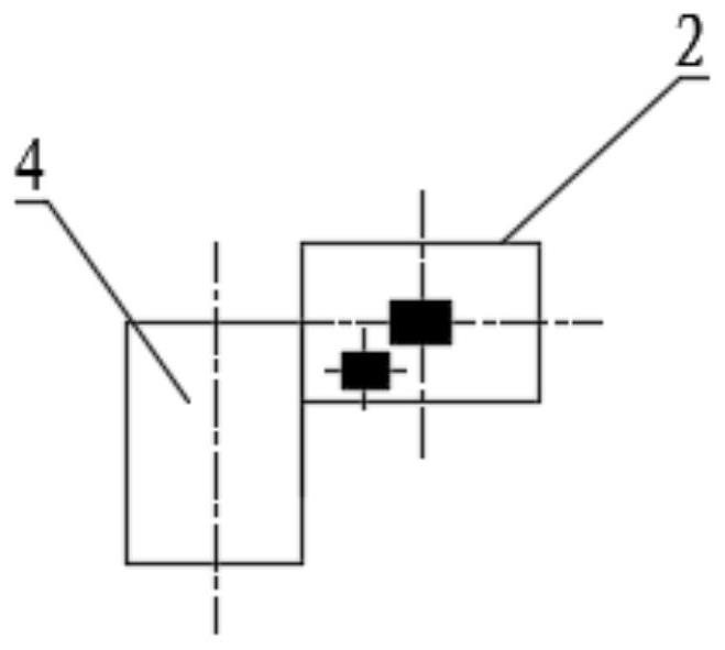
[0059] Target 2 as figure 2 As shown, the background is white, and there are two black positioning rectangles on the white background, wherein the centroid of the first positioning rectangle is A, and the centroid of the second positioning rectangle is B. In this embodiment, for the convenience of illust...

Embodiment 2

[0068] The difference between the on-line monitoring device for the deflection of the main girder 4 of the crane in this embodiment and the first embodiment is that two micro switches are also provided, and the two micro switches are respectively arranged on both sides of the center of the main girder 4. Specifically, the main girder The length of the beam 4 is Z, and it is arranged on both sides of the distance Z / 5 from the center. The deflection of the main beam 4 is only detected when the trolley 5 is operating within the range clamped by the two micro switches.

Embodiment 3

[0070] See Figure 5 , a method for monitoring the deflection of crane girder 4 based on binocular vision of the present embodiment, which includes the following steps,

[0071] Step S1, collecting left camera images and right camera images;

[0072] Step S2, processing the left camera image and the right camera image;

[0073] Step S3, perform three-dimensional reconstruction on the real-time centroid points of the two positioning figures according to the left camera image and the right camera image, and obtain the real-time three-dimensional centroid positions of the first positioning figure and the second positioning figure after real-time reconstruction;

[0074] Step S4. Obtain the real-time deflection value according to the change of the real-time centroid three-dimensional position of the first positioning pattern and the second positioning pattern.

[0075] Wherein, step S2 includes:

[0076] Step S21, correcting the left camera image and the right camera image, and...


PUM


Abstract

The invention discloses a main beam deflection monitoring device based on binocular vision, which comprises at least two cameras and a target, the target is fixedly connected with any main beam of a crane, the target comprises two positioning patterns, the mass center of one positioning pattern is located between the top surface and the bottom surface of the main beam, and the mass center of the other positioning pattern is located between the top surface and the bottom surface of the main beam. The shooting directions of the two cameras face the target, and the two cameras are electrically connected with a controller of the monitoring device, so that the three-dimensional change of the mass center of each positioning graph is monitored. According to the main beam deflection monitoring device based on binocular vision and the monitoring method thereof, a binocular vision system is adopted to calculate the real-time mass center positions of two positioning graphs of a target located on a main beam, the real-time mass center positions are compared with the initial mass center positions of the two positioning graphs, and deformation of the central axis of the main beam is calculated according to changes of the mass center positions; therefore, the deflection value of the main beam is calculated according to the deformation of the main beam of the crane, and the deformation of the main beam of the crane is monitored in real time.

Description

technical field [0001] The invention relates to the technical field of cranes, in particular to a binocular vision-based main girder deflection monitoring device and a monitoring method thereof. Background technique [0002] In order to ensure the safe use of the crane, the deflection of the main girder of the crane needs to be detected during the use of the crane to ensure that the deflection is within a safe range. The traditional method uses methods such as wire drawing measurement method, theodolite method, level method, and connector method to measure manually. Not only time-consuming and labor-intensive but also affected by human factors. For this reason, two improvement schemes have been proposed in the prior art. One is to use the image visual sensing method to regularly detect the deflection of the main girder. One method is to use a laser range finder to detect the change of the distance between the main beam and the ground. The disadvantage is that it can only de...

Claims


Application Information

Patent Timeline
Patent Type & Authority Applications(China)
IPC IPC(8): G01M5/00G01B11/16
CPCG01M5/0025G01M5/0075G01B11/16
Inventor 何祖恩刘毅杨天雪陈旻刘爱国
Owner FUJIAN SPECIAL EQUIP TESTING RES INST
Why Eureka
Try Eureka