
Vibratory rotary grate and boiler

A technology of rotating grate and grate, which is applied in the direction of rotary grate, rocking grate, grate, etc., can solve the problems of insufficient combustion of materials and failure of ash and slag to fall in time.

Pending Publication Date: 2022-03-04
JIANGSU UNIV +1
View PDF2 Cites 0 Cited by
  • Summary
  • Abstract
  • Description
  • Claims
  • Application Information

AI Technical Summary

Problems solved by technology

[0006] The purpose of the present invention is to provide a vibrating rotary grate, which is used to solve the technical problems of insufficient combustion of materials and failure of ash to fall in the existing grate structure.

Method used


Image

  • Vibratory rotary grate and boiler
  • Vibratory rotary grate and boiler

Examples


Embodiment Construction

[0044] In order to better understand the technical content of the present invention, specific embodiments are given together with the attached drawings for description as follows.

[0045]Aspects of the invention are described in this disclosure with reference to the accompanying drawings, which show a number of illustrated embodiments. Embodiments of the present disclosure are not necessarily intended to include all aspects of the invention. It should be appreciated that the various concepts and embodiments described above, as well as those described in more detail below, can be implemented in any of numerous ways, since the concepts and embodiments disclosed herein are not limited to any implementation. In addition, some aspects of the present disclosure may be used alone or in any suitable combination with other aspects of the present disclosure.

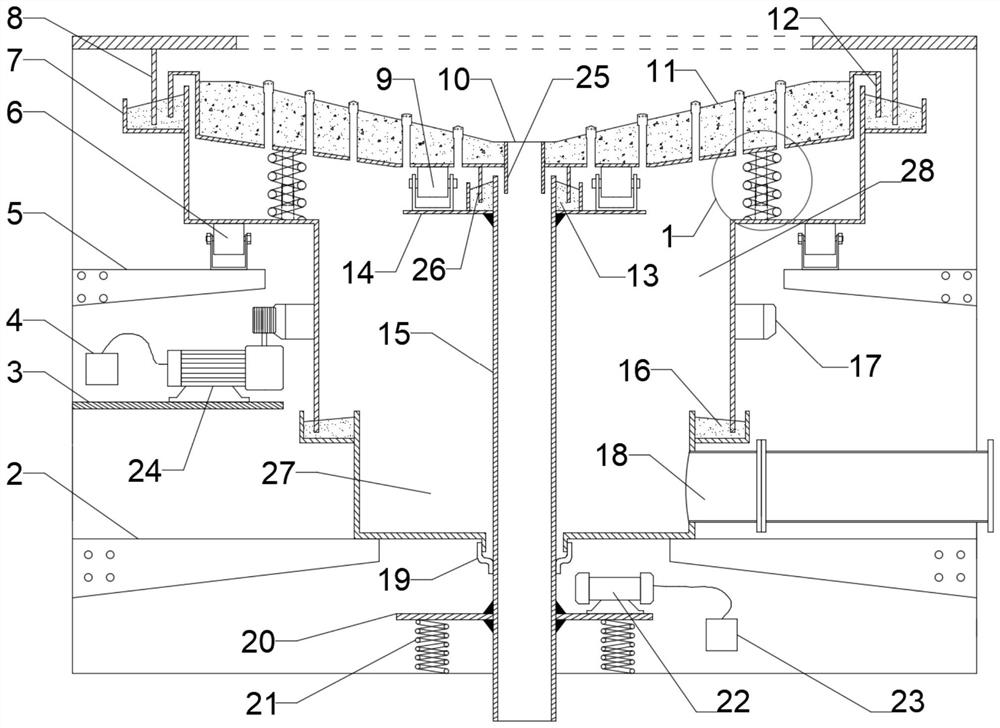
[0046] like figure 1 Shown is a schematic structural view of a vibrating rotary grate provided by an embodiment of the prese...


PUM


Abstract

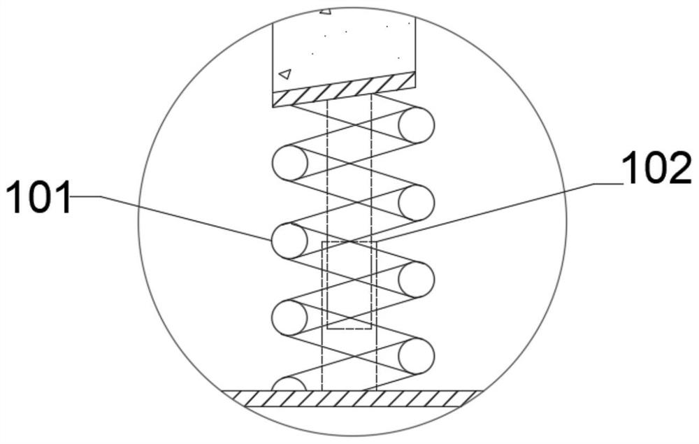
The invention provides a vibrating rotary fire grate and a boiler. The fire grate comprises a fire grate face. The grate face of the fire grate has the freedom degree of vibration and rotation. The slag discharging pipe is used for supporting the grate surface of the fire grate; the air chamber comprises a rotating air chamber and a fixed air chamber which are sequentially arranged in the longitudinal direction of the fire grate; the vibration power source transmits vibration in the longitudinal direction of the fire grate to the slag discharging pipe and the fire grate face through a vibration transmission assembly. The rotating power source transmits rotation around the central axis of the fire grate to the chamber wall of the rotating air chamber through a rotating transmission assembly; the transmission assembly is arranged between the grate surface of the fire grate and the chamber wall of the rotating air chamber and comprises an elastic component and a sleeve component; the elastic component supports the grate face of the grate in the longitudinal direction of the grate. The sleeve part enables the grate face of the fire grate and the chamber wall of the rotating air chamber to be kept synchronous in the rotating direction along the center axis of the fire grate through the sleeve part. The structure can achieve the effects of uniform materials, sufficient combustion and effective discharge of slag.

Description

technical field [0001] The invention relates to the field of boiler grate, in particular to a vibrating rotary grate device. Background technique [0002] As the price of fossil energy continues to rise, the utilization value of biomass energy is getting higher and higher. Wood waste or plant fuel is used as boiler fuel to replace coal or fuel oil, which not only saves non-renewable fossil energy and energy consumption costs, but also has high calorific value, high purity, and no sulfur and phosphorus. With these advantages, biomass boilers are widely used. [0003] However, existing biomass boilers have phenomena such as stockpiling, carbon formation, and ash accumulation, which seriously affect the utilization efficiency of biomass fuels. [0004] Patent CN 213066148U provides a rotary grate for a biomass boiler. The device is provided with a funnel-shaped grate with a large top and a small bottom. The rotational centrifugal force received by the fuel cancels each other...

Claims


Application Information

Patent Timeline
IPC IPC(8): F23H9/00F23H17/00F23L1/02
CPCF23H9/00F23H17/00F23L1/02
Inventor 徐惠斌惠进张闯练平周锦涛郭凯庄伟
Owner JIANGSU UNIV
Learn More