Crank arm sliding block plasma vibration ball mill

A plasma and vibrating ball technology, applied in grain processing and other fields, can solve the problems of low energy conversion efficiency, unfriendly environment, loud noise, etc., and achieve the effect of compact structure, environmental friendliness and low noise

Pending Publication Date: 2021-01-29
SOUTH CHINA UNIV OF TECH
View PDF0 Cites 0 Cited by
  • Summary
  • Abstract
  • Description
  • Claims
  • Application Information

AI Technical Summary

Problems solved by technology

[0005] The purpose of the present invention is to provide a plasma vibration ball mill with a curved arm slider for the problems of low energy conversion efficiency, high noise, large volume, and unfriendly environment during use of the existing mechanical vibration vibration ball mill equipment.

Method used


Image

  • Crank arm sliding block plasma vibration ball mill
  • Crank arm sliding block plasma vibration ball mill
  • Crank arm sliding block plasma vibration ball mill

Examples


Embodiment Construction

[0096] Specific embodiments of the present invention will be described in detail below in conjunction with accompanying drawings:

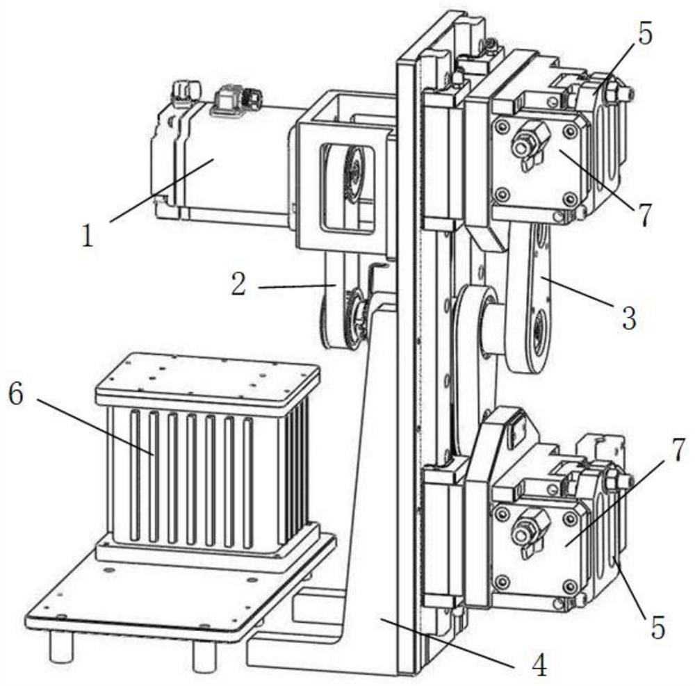
[0097] Such as figure 1 As shown, a curved arm slider plasma vibration ball mill includes a base mechanism 4, a power mechanism 1 arranged on the base mechanism, a transmission mechanism 2 installed on the base mechanism 4 and connected to the power mechanism, and installed on the base mechanism. The ball milling pot clamping mechanism 5 on the seat mechanism 4, the curved arm slider mechanism 3 connected with the transmission mechanism 2, the ball milling pot assembly 7 installed on the ball milling pot clamping mechanism 5, and the same plane as the base mechanism 4 Plasma high voltage discharge system6. The power mechanism transmits power to the crank arm movable block mechanism through the transmission mechanism, and drives the ball mill jar clamping mechanism and the ball mill jar assembly to move up and down through the crank arm slider str...


PUM


Abstract

The invention discloses a crank arm sliding block plasma vibration ball mill. The ball mill comprises a base mechanism, a power mechanism on the back surface of the base mechanism, a transmission mechanism on the back surface of the base mechanism and connected with the power mechanism, a ball-milling tank clamping mechanism at the front of the base mechanism, a ball-milling tank assembly on the ball-milling tank clamping mechanism, a crank arm movable block mechanism connected with the transmission mechanism and the ball-milling tank clamping mechanism at the same time and a plasma high-voltage discharge system. The power mechanism transmits power to the crank arm movable block mechanism through the transmission mechanism and drives the ball-milling tank clamping mechanism and the ball-milling tank assembly to move up and down through a crank arm sliding block structure. A mechanical structure can be well matched with a plasma high-voltage electrode, and the desktop type crank arm sliding block plasma ball mill is achieved. On one hand, high-frequency, high-amplitude and high-gravitational acceleration motion of grinding balls in a ball-milling tank can be achieved, on the other hand, the motion mode of the ball-milling tank has a good protection effect on an introduced high-voltage line, and safety and reliability are achieved.

Description

technical field [0001] The invention belongs to the field of vibration ball milling devices, in particular to a crank arm slider vibration ball milling device, which is suitable for dry grinding environments, discloses a mechanical vibration ball milling technology, and discloses the application of cold field plasma discharge technology to the equipment. Background technique [0002] Vibrating ball mill is a kind of chemical machinery, which is mainly composed of frame, vibrator, grinding tank, electric control system, cooling system, grinding medium, etc. It can grind the material to micron level by forming a strong impact crushing and grinding effect on the material. Equipment. The main working principle is that the motor drives the shaft equipped with the eccentric block to generate vibration through the winding coupling, and transmits it to the bracket. A ball mill cylinder is installed on the bracket, so the powder vibrates accordingly. Both sides and the bottom of th...

Claims


Application Information

Patent Timeline
IPC IPC(8): B02C17/10B02C17/14B02C17/24B02C17/18
CPCB02C17/10B02C17/14B02C17/18B02C17/1815B02C17/24
Inventor 朱敏鲁忠臣许海峰许辉勇章兴石白钢印胡仁宗曾美琴欧阳柳章
Owner SOUTH CHINA UNIV OF TECH
Why Eureka
Try Eureka