Tractor for rail and road
A tractor and dual-purpose technology, which is applied to track and road dual-purpose vehicles, traction connectors, motor vehicles, etc., can solve the problems of complex structure, inability to realize self-locking, inconvenient operation, etc., to achieve simple operation and improve safety performance. and work efficiency, improve the effect of stability
- Summary
- Abstract
- Description
- Claims
- Application Information
AI Technical Summary
Problems solved by technology
Method used
Image

Examples
Embodiment 1
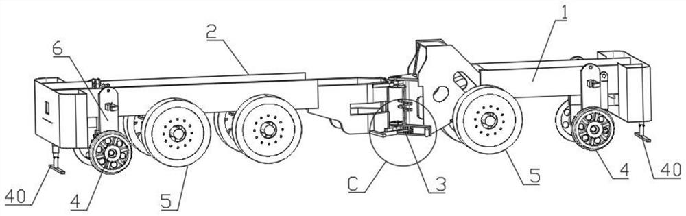
[0045] Such as figure 1As shown, one rail line dual-use tractor of this embodiment includes a front frame 1 and a rear frame 2; the front frame 1 is hinged and the rear frame 2 is hinged, and self-locking device 3 The front frame 1 and the rear frame 2 are provided with a guide wheel 4 and a drive wheel 5; the guide wheel 4 is provided with a guide wheel self-locking device 6, the front frame 1 and the rear frame 2 Both the bike bridge use a splicing bike bridge.
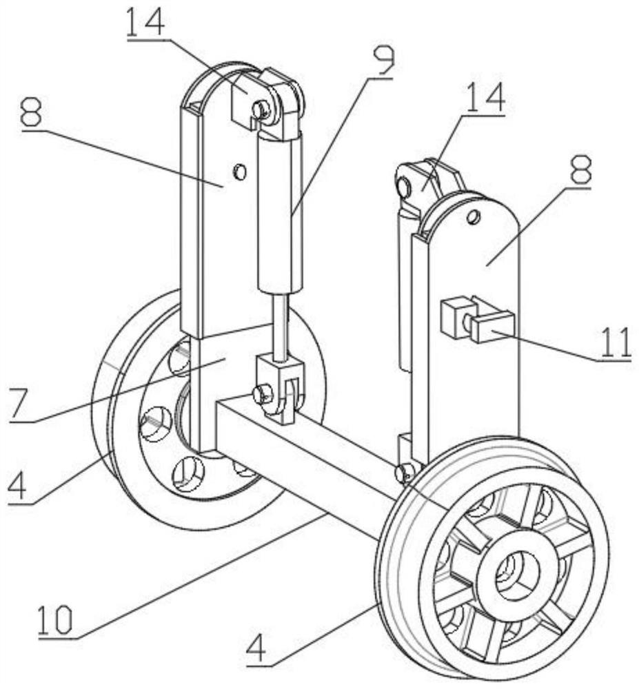
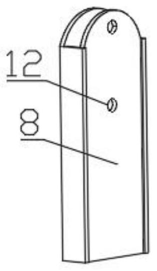
[0046] Such as Figure 2-4 As shown, the guide wheel self-locking device 6 includes a lifting arm 7, a guide frame 8, and a hydraulic cylinder 9; the lifting arm 7 is nested within the guide frame 8, the hydraulic cylinder 9 is mounted in the guide frame through the ear plate 14 8 On the lower end side of the lifting arm 7, the guide wheel 4 is attached to the lower end of the lower end of the lift arm 7, and the hydraulic cylinder 9 is vertically mounted on the guide frame 8 side, the output terminal and the connection ...
Embodiment 2
[0062] Such as Figure 14-16 As shown, one railway two-use tractor according to the present embodiment is substantially the same as that of Example 1, and the difference is that the bridge axle 24 of the split bridge is close to the vehicle bridge main body 22 end. There is a protective mechanism 26, the guard mechanism 26 includes an outer sleeve 27 fixed to the bridge shaft 24, an inner sleeve 28 that is attached to the outer sleeve 27; the inner sleeve 28 is side and the outer sleeve 27 A spring 29 is provided between the outer side, and the spring 29 is connected to the outer side of the inner sleeve 28, and the inner sleeve 28 is threaded with the outer sleeve 27 end, in particular, the inner sleeve 28 is provided with an external thread. The outer sleeve 27 is provided, and the inner sleeve 28 is connected to the threaded connection of the outer sleeve 27. When the external deviation impacts against the bridge shaft 24, the above setting can be effectively protected against t...
Embodiment 3
[0064] Such as Figure 17As shown, one rail line dual-use tractor according to the present embodiment is substantially the same as in Example 1, which is different in that the handle 33 of the tractor cutting device 40 is connected by connecting block 37 and mounting The upper and lower drive device 38 on the side of the outer cylinder 30 is connected to the connecting block 37 detachable connection, such as the handle 33 and the connecting block 37 are connected by bolts 39. The upper and lower driving device 38 can employ an electric push rod, a cylinder, a cylinder, or the like. When used, the positioning pin 34 is removed, and the handle 33 is driven by the upper and lower drive unit 38 to adjust the inner cylinder 31 and the position of the snowboard 32 to achieve automatic adjustment of the position of the snowboard 32. When the upper and lower drive unit 38 is damaged or other reasons cannot be activated, the bolt 39 can be removed, so that the handlebar 33 is separated from...
PUM
 Abstract
Description
Claims
Application Information
 - R&D
- Intellectual Property
- Life Sciences
- Materials
- Tech Scout
- Unparalleled Data Quality
- Higher Quality Content
- 60% Fewer Hallucinations
Browse by: Latest US Patents, China's latest patents, Technical Efficacy Thesaurus, Application Domain, Technology Topic, Popular Technical Reports.
© 2025 PatSnap. All rights reserved.Legal|Privacy policy|Modern Slavery Act Transparency Statement|Sitemap|About US| Contact US: help@patsnap.com