Eureka AIR delivers breakthrough ideas for toughest innovation challenges, trusted by R&D personnel around the world.

System for converting thermal energy into mechanical energy

A technology of mechanical energy and thermal energy, applied in the system field, can solve problems such as loss and achieve the effect of increasing density

Pending Publication Date: 2022-03-01
SIEMWNS ENERGY GLOBAL GMBH & CO KG
View PDF8 Cites 0 Cited by
  • Summary
  • Abstract
  • Description
  • Claims
  • Application Information

AI Technical Summary

Problems solved by technology

This results in the compressor or pump having to do a relatively large amount of compression work
[0008] Because compression is associated with losses, this means that, for example, in a water vapor circuit a low compression work results in small losses, while e.g. in sCO 2 High compression work in the circuit leads to large losses

Method used


Image

  • System for converting thermal energy into mechanical energy
  • System for converting thermal energy into mechanical energy
  • System for converting thermal energy into mechanical energy

Examples


Embodiment Construction

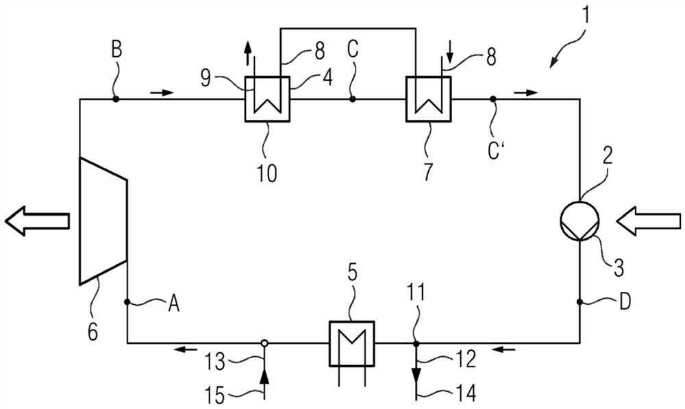
[0029] figure 1 A conventional circuit 1 as already explained above is shown.

[0030] figure 2 A circuit 1 according to the invention is shown. exist figure 1 The circuit shown in and in the figure 2 The difference between the circuits 1 according to the invention shown in , is as follows: Between the condenser 4 and the pump 3 a cooling unit 7 is arranged. The condenser 4 is operated with cooling water 8 at which the flow medium is condensed. Cooling water 8 flows via pipe 9 into the condenser housing 10 .

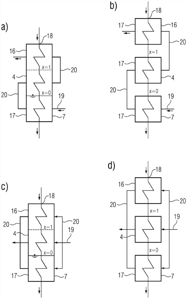
[0031] The cooling unit 7 is designed to further cool the liquid flow medium. In one embodiment, the liquid flow medium is operated with cooling water 8 . in targeting image 3 A detailed description of the cooling assembly 7 is given in the description of .

[0032] The fluid medium is CO 2 , especially sCO 2 .

[0033] exist figure 2 The circuit shown in can be used in geothermal applications. For this purpose, no separate components are used in the ge...


PUM


Abstract

The invention relates to a system comprising: a pump (3) for conveying a flow medium; an assembly (5) for converting the flow medium from a liquid state to a gaseous state; a fluid machine (6) for converting thermal energy of the flow medium into mechanical energy; a condenser (4) for condensing the gaseous flow medium into a liquid state, a cooling unit (7) for cooling the liquid flow medium being arranged upstream of the pump (3) in order to reduce the compression work.

Description

technical field [0001] The invention relates to a system comprising: a pump for conveying a flow medium; an assembly for converting the flow medium from a liquid state to a gaseous state; a fluid machine for converting thermal energy of the flow medium Converted into mechanical energy; condenser, which is used to condense the gaseous flow medium into a liquid state. Background technique [0002] Thermal processes can be carried out in a closed fashion. An example of a closed thermal process is a water-steam circuit in a power plant for the production of electrical energy. Here, water or steam is used as heat carrier and working medium. This cyclic process is called the Clausius Rankine Prozess. [0003] At low process temperatures, the cyclic process also operates with organic flow media. This cycle process is called Organic Rankine Cycle (Organic Rankine Cycle). [0004] Although the fluid medium in an Organic Rankine cycle is not strictly pure water vapor, the fluid m...

Claims


Application Information

Patent Timeline
Patent Type & Authority Applications(China)
IPC IPC(8): F01K9/00F01K25/10
CPCF01K9/00F01K25/103Y02E10/10F01K9/003F03G4/033F03G4/02F03G4/026F28B1/02F28B9/04
Inventor S·格罗斯S·格罗特坎普R·祖德霍夫M·韦克松
Owner SIEMWNS ENERGY GLOBAL GMBH & CO KG
Why Eureka
Eureka Blog
Learn More