


Quick Research
Generate reliable direction feasibility study reports for your R&D in just a few steps.

Technical Q&A
Discover and master advanced knowledge NOW. Basics, ideas, possibilities, all at once.

Find Solutions
As an expert in R&D theories, this can generate solutions to your technical problems instantly.

Evaluate Feasibility
Analyze your overall solution with one click, know your potential R&D risks in advance.

Monitor Landscape
Get weekly tech updates, stay abreast of the latest tech innovations and key insights.
Beam position detector for proton and heavy ion synchrotron and use method
A synchrotron, proton heavy ion technology, applied in radiation measurement, instruments, measuring devices, etc., can solve the problems such as not suitable for strong current annular proton heavy ion annular accelerator, large beam coupling impedance, mechanical complexity, etc. The effect of less resonance, low beam coupling impedance and low cost
- Summary
- Abstract
- Description
- Claims
- Application Information
AI Technical Summary
Problems solved by technology
Method used
Image

Examples
Embodiment 1
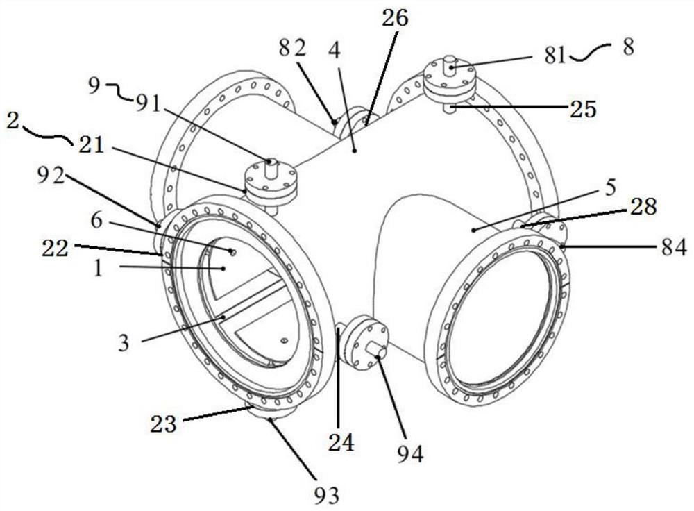
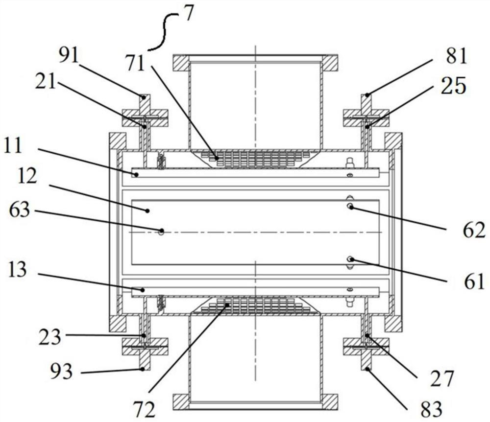
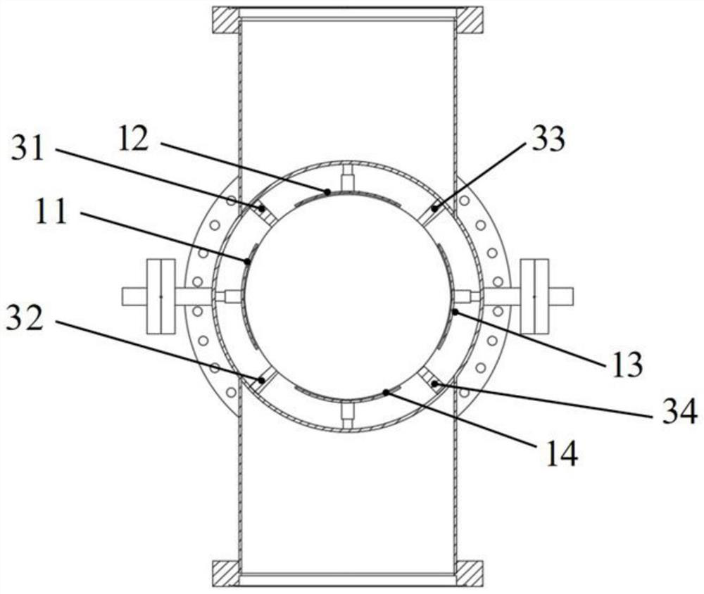
[0046] Such as figure 1 As shown, this embodiment provides a beam position detector for a proton heavy ion synchrotron, which includes a plate assembly 1, a vacuum feedthrough assembly 2, an isolation ground assembly 3, a vacuum pipeline 4, a vacuum pump port 5, a support Column assembly 6, load 8 and low noise amplifier 9. Among them, the plate assembly 1 is fixedly arranged on the inner wall of the vacuum pipeline 4 through the support column assembly 6, and is separated by the isolation ground assembly 3; the vacuum feedthrough assembly 2 is arranged on the outer wall of the vacuum pipeline 4, and the ultra-high vacuum feedthrough assembly 2 They are respectively connected to the plate assembly 1, the load 8 or the low noise amplifier 9; a vacuum pump port 5 is provided symmetrically on both sides of the vacuum pipe 4, and the two vacuum pump ports 5 are connected to the vacuum pump through the vacuum pump pipe to ensure the vacuum degree in the vacuum pipe 4. The electrod...
Embodiment 2
[0057] Based on the beam position detector for a proton heavy ion synchrotron provided in Embodiment 1, this embodiment provides a method for using a beam position detector for a proton heavy ion synchrotron, including the following:
[0058] 1) Determine the beam position measurement mode of the proton heavy ion synchrotron, if it is the high-current circular accelerator beam position measurement mode, then enter step 2), if it is the weak current circular accelerator beam position measurement mode, then enter step 3) , if it is the beam position measurement mode of the medical ion synchrotron, go to step 4).
[0059] Wherein, the high-current circular accelerator in the embodiment of the present invention refers to that the number of particles is more than 1×10 9 even up to 1×10 13 Accelerators; Weak flow circular accelerator refers to the number of particles less than 1×10 9 The accelerator; and the medical ion synchrotron is also a kind of weak flow circular accelerator,...
PUM
| Property | Measurement | Unit |
|---|---|---|
| Thickness | aaaaa | aaaaa |
| Longitudinal length | aaaaa | aaaaa |
| Width | aaaaa | aaaaa |
Abstract
Description
Claims
Application Information
 - R&D Engineer
- R&D Manager
- IP Professional
- Industry Leading Data Capabilities
- Powerful AI technology
- Patent DNA Extraction
Browse by: Latest US Patents, China's latest patents, Technical Efficacy Thesaurus, Application Domain, Technology Topic, Popular Technical Reports.
© 2024 PatSnap. All rights reserved.Legal|Privacy policy|Modern Slavery Act Transparency Statement|Sitemap|About US| Contact US: help@patsnap.com