Sectional material clamping upside-down hanging table type equipment

A profile and desktop technology, which is applied in the field of profile clamping and upside-down desktop equipment, can solve the problems of precision parts that cannot ensure the face-to-face contact between the heated workpiece and the support, poor heat resistance, time-consuming and labor-intensive problems, etc., to avoid bumps and scratches The effect of improving the surface of the workpiece, improving the pass rate and quality, and reducing noise

Pending Publication Date: 2022-03-01
潍坊新松机器人自动化有限公司
View PDF0 Cites 0 Cited by
  • Summary
  • Abstract
  • Description
  • Claims
  • Application Information

AI Technical Summary

Problems solved by technology

However, the disadvantage of this method is that the installation height of the vibrating plate must be set at twice the height of the diathermy furnace, and the profiles must be lifted from the ground to this height, which not only takes time and effort, but also poses a safety hazard
In addition, the biggest disadvantage of the vibrating plate is the noise, because the working principle of the vibrating plate is that all the short bars in the plate vibrate with the power frequency of the plate body, generally more than 80 decibels, there is noise pollution
The other is robot feeding, which has poor heat resistance and cannot guarantee the face-to-face contact between the heated workpiece and the bracket for the heat treatment of precision parts.

Method used


Image

  • Sectional material clamping upside-down hanging table type equipment
  • Sectional material clamping upside-down hanging table type equipment
  • Sectional material clamping upside-down hanging table type equipment

Examples


Embodiment Construction

[0029] In describing the present invention, it should be understood that the terms "center", "longitudinal", "transverse", "length", "width", "thickness", "upper", "lower", "front", " Orientation or position indicated by "back", "left", "right", "vertical", "horizontal", "top", "bottom", "inner", "outer", "clockwise", "counterclockwise", etc. The relationship is based on the orientation or positional relationship shown in the drawings, and is only for the convenience of describing the present invention and simplifying the description, rather than indicating or implying that the referred device or element must have a specific orientation, be constructed and operated in a specific orientation, therefore It should not be construed as a limitation of the present invention.

[0030] In addition, the terms "first" and "second" are used for descriptive purposes only, and cannot be interpreted as indicating or implying relative importance or implicitly specifying the quantity of indic...


PUM


Abstract

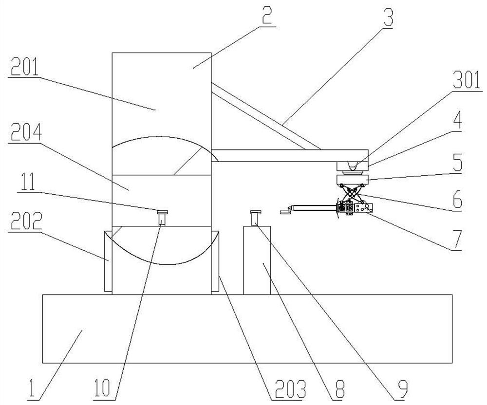
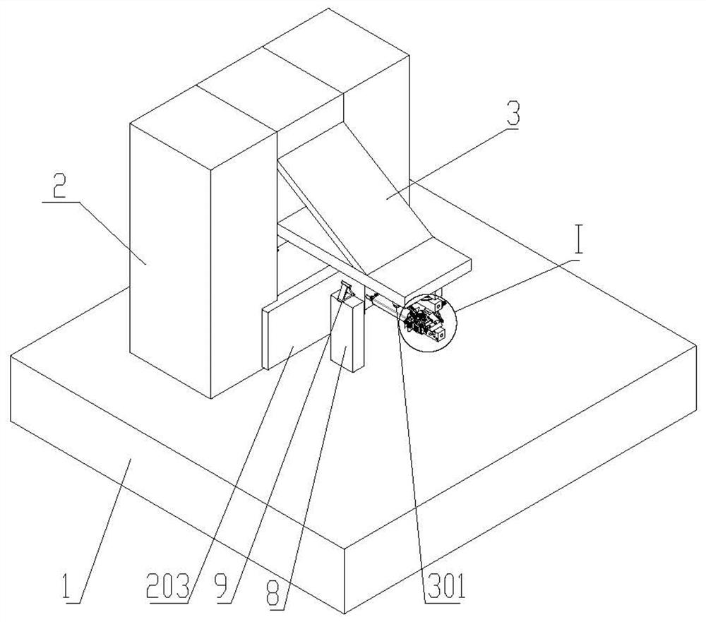
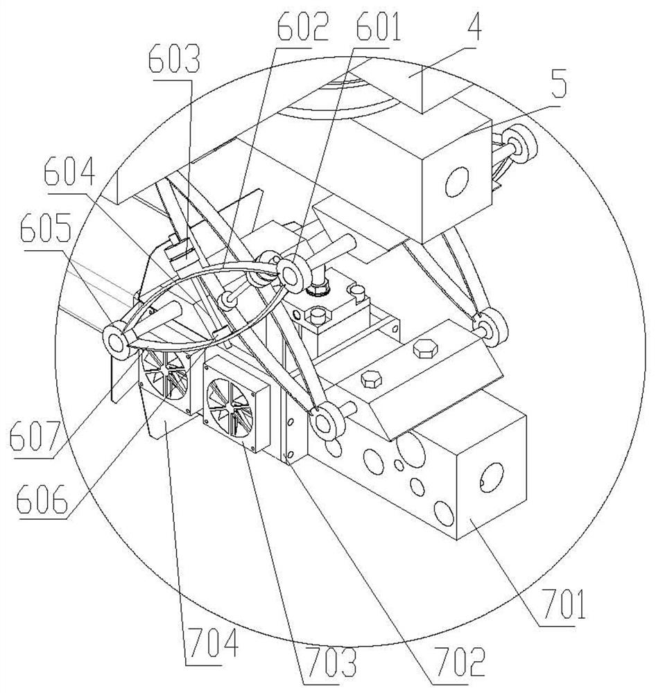
The invention relates to table type equipment, in particular to sectional material clamping inverted hanging table type equipment. Comprising a heat treatment furnace, a suspension support, a walking sliding plate, a rotating table, a flexible driving mechanism and a movable clamping platform, the suspension support is arranged above a feeding port of the heat treatment furnace, a linear module capable of outputting power in the direction close to or away from the feeding port is arranged at the bottom of the suspension support, and the walking sliding plate is connected with the linear module; a rotating table is arranged below the walking sliding plate, the lower portion of the rotating table is connected with the two sides of a movable clamping platform through two flexible driving mechanisms, the flexible driving mechanisms are used for adjusting the posture of the movable clamping platform, and the movable clamping platform is used for clamping profiles for feeding or discharging. The device has the advantages of large working radius, high working efficiency, low noise and the like, and a large amount of labor is saved; and the device is simple in structure, reliable in work and low in manufacturing cost and maintenance cost.

Description

technical field [0001] The invention relates to desktop equipment, in particular to a profile clamping upside-down desktop equipment. Background technique [0002] In the forging industry, at the front end of the forging press, that is, the front end of the diathermy furnace, the loading of various profiles has always been the heaviest work. At present, there are three feeding methods for diathermy furnaces. One is that the operator uses manual clamps one by one to manually clamp and feed into the furnace mouth, which is not only labor-intensive but also has the risk of being scalded and burned; The advanced vibration feeding method, the vibration plate can already meet the requirements in terms of improving productivity. However, the disadvantage of this method is that the installation height of the vibrating plate must be set at twice the height of the diathermy furnace, and the profiles must be lifted from the ground to this height, which not only takes time and effort, ...

Claims


Application Information

Patent Timeline
IPC IPC(8): F27D3/00B21J17/00
CPCF27D3/0025F27D3/0024F27D3/0084B21J17/00F27D2003/0046F27D2003/0068Y02P10/20
Inventor 关盛楠王化明周兆爽朱维金于辉
Owner 潍坊新松机器人自动化有限公司
Why Eureka
Try Eureka