
Mining drill rod changing manipulator

A manipulator and mine-used technology, which is applied to drill pipes, drill pipes, drilling equipment, etc., can solve problems such as difficult operation for workers, and achieve the effects of simple manipulation, large working radius, and large driving force

Pending Publication Date: 2021-07-13
徐州富锲机电科技有限公司
View PDF0 Cites 0 Cited by
  • Summary
  • Abstract
  • Description
  • Claims
  • Application Information

AI Technical Summary

Problems solved by technology

[0004] Technical problem to be solved: Aiming at the above technical problems, the present invention provides a mining drilling manipulator, which can effectively solve the problem of difficult operation for workers when drilling pipes are spliced ​​and disassembled

Method used


Image

  • Mining drill rod changing manipulator
  • Mining drill rod changing manipulator

Examples


Embodiment 1

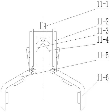
[0023] like figure 1 and figure 2 As shown, a mining drill changing manipulator includes a base 1 , a slewing bearing 2 , a lifting part, a translation part and a gripper assembly 11 .

[0024] The slewing bearing 2 is connected to the fixed base 1 and the bottom of the outer end of the inner sleeve 3 of the lifting part.

[0025] The inner bottom of the lift inner sleeve 3 is hinged to one end of the lift cylinder 5 , and the other end of the lift cylinder 5 is hinged to the inner top of the lift outer sleeve 4 sleeved outside the lift inner sleeve 3 . The outer sleeve 4 of the elevating part and the inner sleeve 3 of the elevating part adopt clearance fit. In order to facilitate the installation of the inner sleeve 3 of the lifting part, there are holes for the installation of the pin shaft and the oil outlet of the lifting cylinder 5 .

[0026] The top outer end of the outer sleeve 4 of the lifting part is fixed by the flange 6 to the outer sleeve 7 of the translation p...


PUM


Abstract

The invention discloses a mining drill rod changing manipulator, and belongs to the technical field of mining mechanical equipment. The mining drill rod changing manipulator comprises a base, a slewing bearing, a lifting part, a translation part and a gripper assembly; the slewing bearing is arranged between the base and the lifting part; the lifting part is vertically arranged and is used for controlling the vertical lifting of the manipulator; the translation part is horizontally arranged and used for controlling the horizontal movement of the manipulator, and one end of the translation part is fixedly connected with the top end of the lifting part through a flange; the gripper assembly is vertically arranged and comprises a gripper opening and closing oil cylinder, a fixing frame, a four-bar mechanism, a left holding claw and a right holding claw; the fixing frame is arranged on the gripper opening and closing oil cylinder; the top end of the gripper opening and closing oil cylinder is in transmission connection with the translation part through a swing oil cylinder, and the bottom end of the gripper opening and closing oil cylinder is fixedly connected with the top end of the four-bar mechanism; the bottom end of the four-bar mechanism controls the left holding claw and the right holding claw correspondingly; and the top end of the left holding claw and the top end of the right holding claw are both hinged to the fixing frame. The problem that when drill rods are spliced and disassembled, operation of workers is difficult can be effectively solved.

Description

technical field [0001] The invention belongs to the technical field of mining machinery and equipment, and particularly relates to a mining drill changing manipulator. Background technique [0002] With the increase of mining depth and strength of coal mines, rock bursts are more and more frequent, and the losses caused by them are also increasing. At present, one of the main measures to prevent rock bursts in coal mines is to drill holes in the coal seam to release the coal seam pressure. Use a pressure relief drill for pressure relief work. Most of the currently known pressure relief drilling rigs use an auger rod to drill holes in rock formations. [0003] However, due to the large depth of drilling and the number of drill rods required, it is necessary to connect multiple drill rods end to end to drive into the coal wall; after a drilling is completed, the drill rods must be pulled section by section. In and out of the drill pipe box. Due to the limited space for un...

Claims


Application Information

Patent Timeline
Patent Type & Authority Applications(China)
IPC IPC(8): E21B19/14E21B19/10
CPCE21B19/10E21B19/14
Inventor 罗江南程舒燕侯大为
Owner 徐州富锲机电科技有限公司
Learn More