Railway tank car body and railway tank car

A technology of tank body and tank car, applied in the field of railway tank car body and railway tank car, can solve the problems of insufficient strength of the tank body, pollution of the environment, medium steam escape, etc. The effect of stability

Active Publication Date: 2022-03-01
CRRC SHANDONG CO LTD
View PDF6 Cites 0 Cited by
  • Summary
  • Abstract
  • Description
  • Claims
  • Application Information

AI Technical Summary

Problems solved by technology

[0003](1) The tank body of the existing railway tank car is usually a one-piece straight cylinder structure or a variable section structure with a flat top and inclined bottom (the bottom is from the two ends of the cylinder to the middle section Downward slope), the two ends of the tank body are installed on the bottom frame through the end support; the tank body and the internal medium are mainly supported by the bottom frame and the end support, and the strength of the tank body itself is not enough; (2) The traditional railway tank car is generally The medium is loaded and unloaded through the manhole on the top of the tank body, which has a single function, and the manhole is kept open during the loading and unloading process, which may easily cause the medium steam to escape into the air and pollute the environment; (3) The structure of the existing railway tank car is relatively heavy and cannot meet the requirements. Lightweight requirements

Method used


Image

  • Railway tank car body and railway tank car
  • Railway tank car body and railway tank car
  • Railway tank car body and railway tank car

Examples


Embodiment 1

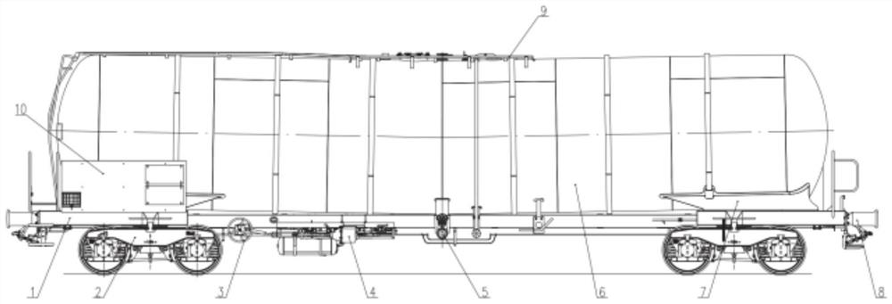
[0037] This embodiment provides a railway tank car body, such as figure 1 As shown, it includes a tank assembly 6, a chassis assembly 1, a loading and unloading system 5, and a tank bracket assembly 7. The tank assembly 6 is installed on the chassis assembly 1 through the tank bracket assembly 7, and the loading and unloading system 5 Installed on tank body assembly 6.

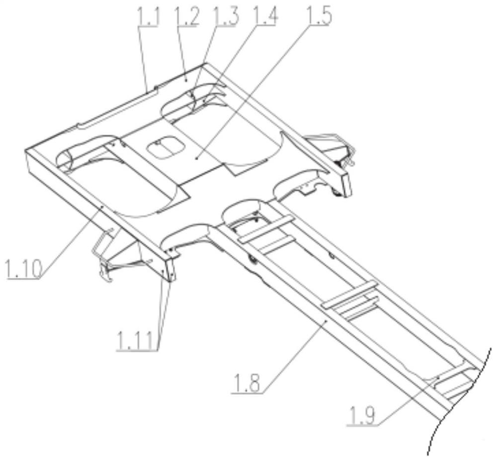
[0038] In order to meet the lightweight requirements of the car body and meet the strength requirements under normal working conditions, the underframe assembly 1 of this embodiment adopts the structural form of "stretch pillow + center beam", and the two ends of the center beam are respectively connected to the traction pillow. like figure 2 As shown, the traction pillow includes an end beam, a traction beam 1.5, a corbel and a side beam 1.10, and the traction beam 1.5 is a hollow structure, one end of which is connected to the end beam, and the other end is connected to the corbel to form an I-shaped struc...

Embodiment 2

[0070] This embodiment provides a kind of railway tank car, such as figure 1 As shown, it includes the railway tank car body described in Embodiment 1, and also includes a bogie 2, a parking brake device 3, and an air brake device 4. Both ends of the chassis assembly 1 are equipped with bogies 2, and the parking The vehicle brake device 3 and the air brake device 4 are respectively installed on the bottom of the chassis assembly 1 through the hanger, and are located below the first cylinder 6.2 or the second cylinder 6.3.

[0071] The coupler buffer device 8 is installed on the outside of the end beam of the underframe assembly 1 through bolts; The transverse central plane of frame composition 1 overlaps, and suitable space is reserved for the two ends of chassis assembly 1, walks the platform with the end of welding platform assembly 9, makes full use of the longitudinal space of chassis assembly 1.

[0072]The outer side of one end of the tank body assembly 6 and the outer ...


PUM


Abstract

The invention discloses a railway tank car body and a railway tank car, and belongs to the technical field of railway vehicle equipment.The railway tank car body comprises an underframe assembly, a tank body assembly and a loading and unloading system, the tank body assembly is installed on the underframe assembly through a tank body support assembly, and the loading and unloading system is installed on the tank body assembly; the tank assembly comprises a first cylinder and a second cylinder, the ends of the first cylinder and the second cylinder are in butt joint, and a set included angle is formed between the axes of the first cylinder and the second cylinder. The loading and unloading system comprises a bottom valve and a bottom valve control mechanism connected with the bottom valve, and an automatic ventilation valve is installed at the top of the first barrel or the second barrel and connected with the bottom valve through a linkage mechanism. The requirement for light weight of a vehicle body can be met, various light oil medium loading and unloading modes can be achieved, it is guaranteed that medium steam does not escape or leak and can be recycled, and the safety of a loading and unloading system under unforeseen circumstances is met.

Description

technical field [0001] The invention relates to the technical field of railway vehicle equipment, in particular to a railway tank car body and a railway tank car. Background technique [0002] The railway tank car is the main special-purpose vehicle used for loading goods such as gas, liquid (such as light oil), powder, etc. on the railway. At present, there are still some problems in traditional railway tank cars in terms of vehicle structure, vehicle weight, safety, and environmental protection. The specific problems are as follows: [0003] (1) The tank body of the existing railway tank car is usually a one-piece straight cylinder structure or a variable-section structure with a flat top and an inclined bottom (the bottom is inclined from the two ends of the cylinder body to the middle section), and the two ends of the tank body are installed on the On the bottom frame; the tank body and the internal medium are mainly supported by the bottom frame and end supports, and t...

Claims


Application Information

Patent Timeline
IPC IPC(8): B61D5/00B61D5/06
CPCB61D5/00B61D5/06Y02T30/00
Inventor 孟策翟鹏军张文龙王力争白云记李烽李兴
Owner CRRC SHANDONG CO LTD
Why Eureka
Try Eureka